


231
IORD Instruction to Transfer Data
Section 5-3
Ladder Program Example
Data after Reading [DM]
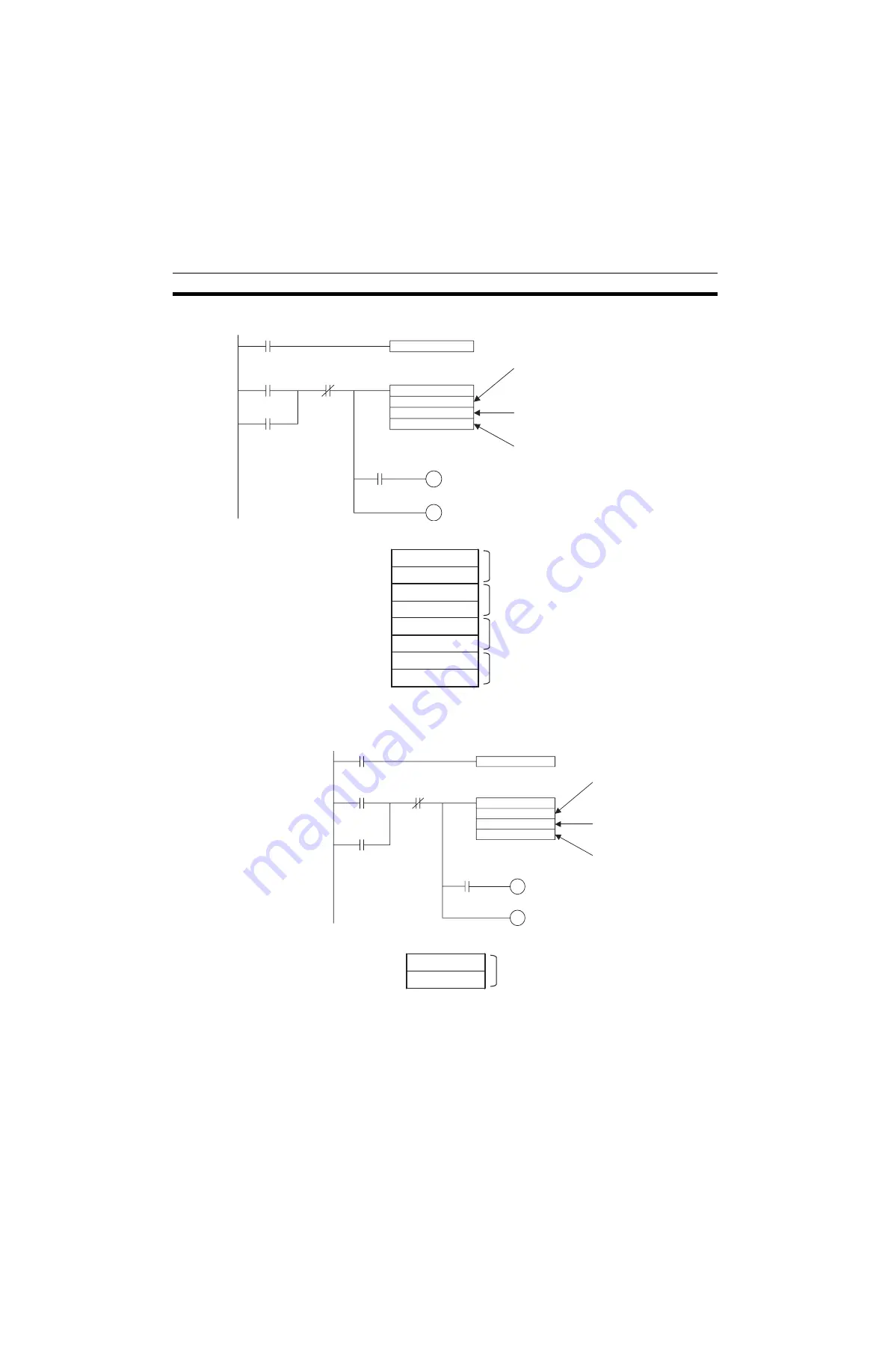
Example 2) Read the Axis 1 Manual Feed Acceleration Time (500[ms]) to
D00100 to D00101.
Ladder Program Example
Data after Reading [DM]
Example 3) Read the servo parameters using IORD instruction
• To read the servo parameters, the servo parameter axis has to be speci-
fied for the IOWR instruction in advance. Write the axis No. in 6000h of
IORD/IOWR control code (address in the MC Unit).
DIFU
R1
R1
R3
R2
IORD
#0456
#00088000
D00100
Execution Condition
(Work bit)
Specifies the address PL0456 Hex as the
first position data address in the MC Unit
No. of transferred words: 8 words
transfer destination unit No.: 0
(Four position data x 2 words = 8 words)
Specifies the first word of destination where
the position data will be stored.
OUT R3
OUT R2
(Work bit)
(Work bit)
=Flag
D00100
BF15
D00101
0034
D00102
614E
D00103
00BC
D00104
FC88
D00105
FDB0
D00106
E240
D00107
0001
←
3456789
←
123456
←
−
38765432
←
12345678
DIFU
R1
R1
R3
R2
IORD
#55C6
#00028000
D00100
Execution Condition
=Flag
OUT R3
OUT R2
(Work bit)
Specifies the address 55C6 Hex as the
Axis 1 manual feed acceleration time
Specifies 2 words as the number of
transfer words and the transfer source
unit No. 0
Specifies the first destination word
where the manual feed acceleration
time will be stored.
(Work bit)
(Work bit)
D00100
01F4
D00101
0000
←
500 [ms]
Summary of Contents for CS1W-MCH71 -
Page 2: ...CS1W MCH71 CJ1W MCH71 Motion Control Unit Operation Manual Revised June 2008 ...
Page 3: ...iv ...
Page 29: ...xxx ...
Page 33: ...xxxiv ...
Page 35: ...xxxvi ...
Page 39: ...xl ...
Page 69: ...24 Performance Section 1 7 ...
Page 99: ...54 Connecting MECHATROLINK Devices Section 3 5 ...
Page 283: ...238 Saving Data Section 5 4 ...
Page 417: ...372 Command Details Section 6 3 ...


