


318
Command Details
Section 6-3
When [Master axis travel distance] < [Master axis travel distance in accelera-
tion] + [Master axis travel distance in acceleration], the actual master axis
travel distance in accele the actual master axis travel distance in
deceleration = [Master axis travel distance] while maintaining the ratio
between the acceleration and deceleration intervals. In this case, the master
axis travel distance at constant speed is 0.
• Master axis input ignores signs, and it is treated as the absolute travel dis-
tance. Therefore, only the signs of [Slave axis travel distance] determine
the direction of the slave axis operation. For example, if the master axis
travel direction is reversed during synchronization, the slave axis travel
direction will not change.
• The link option influences the following operations depending on the set-
ting value.
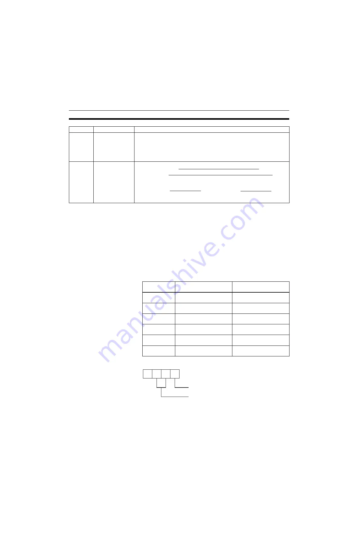
Note
The bit image shown below:
Constant
speed
Master axis travel
distance- Master
axis travel distance
in acceleration- Mas-
ter axis travel dis-
tance in deceleration
[Slave axis travel distance]- Slave axis travel distance in acceleration - Slave axis
travel distance in deceleration
Decelera-
tion
Master axis travel
distance in decelera-
tion
Interval
Master axis
Slave axis
[Slave axis travel
distance]
×
[Master axis travel distance in deceleration]
2
[Master axis
travel distance
in acceleration]
2
+ Master axis
travel distance at
constant speed +
[Master axis
travel distance
in deceleration]
2
Link option
Command execution
completion
Link operation start
0 or omitted
When slave axis travel dis-
tance output is completed
When command execution is
started
1
When command execution is
started
When command execution is
started
2
When slave axis travel dis-
tance output is completed
When latch for master axis is
detected
3
When command execution is
started
When latch for master axis is
detected
4
When slave axis travel dis-
tance output is completed
When master axis reaches
Link start position
5
When command execution is
started
When master axis reaches
Link start position
1
2
4
8
0/1= Slave axis travel distance output
completed/With command execution is started
0/1/2 = When command execution is started/
When latch for master axis is detected/
When master axis reaches Link start position
Summary of Contents for CS1W-MCH71 -
Page 2: ...CS1W MCH71 CJ1W MCH71 Motion Control Unit Operation Manual Revised June 2008 ...
Page 3: ...iv ...
Page 29: ...xxx ...
Page 33: ...xxxiv ...
Page 35: ...xxxvi ...
Page 39: ...xl ...
Page 69: ...24 Performance Section 1 7 ...
Page 99: ...54 Connecting MECHATROLINK Devices Section 3 5 ...
Page 283: ...238 Saving Data Section 5 4 ...
Page 417: ...372 Command Details Section 6 3 ...


