


xxiii
Compliance with RoHS Directive
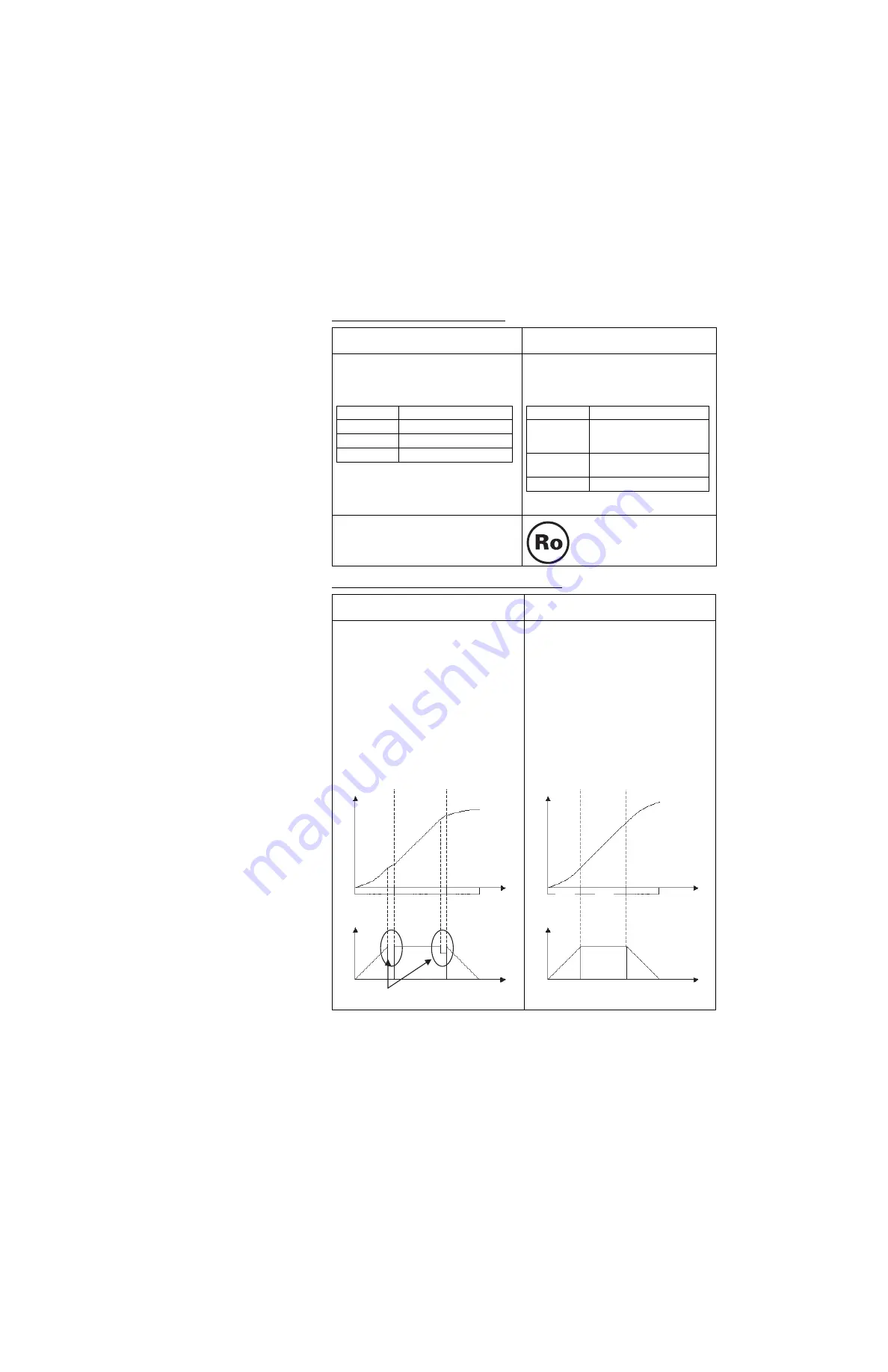
Increased Precision of CAMBOX Command
Previous version
(Unit Ver. 2.0)
Current version
(Unit Ver. 3.0)
Lead was included in the cream solder
used to mount chip components, in the
flow solder used in assembly, and in
thread solder.
As shown below, lead is not used. There
is no change in specifications (including
outer appearance) resulting from this
change.
Note: Either 1 or 2 shown above is used.
There is no mark indicating compliance
with the RoHS Directive.
The RoHS compliance mark
is displayed.
Previous version
(Unit Ver. 2.0)
Current version
(Unit Ver. 3.0)
If the slave axis CAM table is switched
during continuous master axis travel, part
of the slave axis travel is eliminated when
the CAM table is switched.
Example:
:
CAMBOX [J01]1 [J02]10000 K10000 Q8
B0;Cam 1
CAMBOX [J01]2 [J02]10000 K10000 Q8
B0;Cam 2
CAMBOX [J01]3 [J02]10000 K10000 Q8
B0;Cam 3
:
This amount of travel is eliminated.
The slave axis will travel the set amount,
even if the slave axis CAM table is
switched during continuous master axis
travel.
Example:
:
CAMBOX [J01]1 [J02]10000 K10000 Q8
B0;Cam 1
CAMBOX [J01]2 [J02]10000 K10000 Q8
B0;Cam 2
CAMBOX [J01]3 [J02]10000 K10000 Q8
B0;Cam 3
:
Solder type
Main components
Cream solder
Tin and lead
Flow solder
Tin and lead
Thread solder Tin and lead
Solder type
Main components
Cream solder
(1) Tin, silver, indium, and
bismuth
(2) Tin, silver, and copper
Flow solder
(1) Tin and copper
(2) Tin, silver, and copper
Thread solder Tin, silver, and copper
0
0
Slave axis
displacement
Master axis phase
Cam 1
Cam 3
Cam 2
Slave axis speed
Master axis
phase
0
0
Slave axis
displacement
Master axis phase
Cam 1
Cam 3
Cam 2
Slave axis speed
Master axis
phase
Summary of Contents for CS1W-MCH71 -
Page 2: ...CS1W MCH71 CJ1W MCH71 Motion Control Unit Operation Manual Revised June 2008 ...
Page 3: ...iv ...
Page 29: ...xxx ...
Page 33: ...xxxiv ...
Page 35: ...xxxvi ...
Page 39: ...xl ...
Page 69: ...24 Performance Section 1 7 ...
Page 99: ...54 Connecting MECHATROLINK Devices Section 3 5 ...
Page 283: ...238 Saving Data Section 5 4 ...
Page 417: ...372 Command Details Section 6 3 ...


