


563
Coordinate System
Section 9-3
• If origin setting is executed near the limit of the multi-turn data, a slight
movement will make the axis exceed the limit. Therefore, always initialize
the multi-turn data of the encoder before executing origin setting.
• The operation that the axis is used within the ranges where the multi-turn
data is reset or not reset is shown below:
Using as Unlimited Length
Axis
Same as the case of limited length axis, to execute the axis operation within
the range where the multi-turn data is not reset, use the same setting as the
one for the limited length axis. However, to execute the axis operation exceed-
ing the limit of the multi-turn data, it is required to match the reset timing of the
coordinate system managed in the MC Unit and the reset timing of the
encoder’s multi-turn data. To match the timings appropriately, adjust the set-
ting value of the parameter [Pn205: Multi-turn limit setting]. In the case where
the load shaft makes n rotations while the motor makes m rotations, set the
value obtained by subtracting 1 from the denominator of deceleration ratio (m-
1) in Servo Driver parameter Pn205.
Also set the following MC Unit parameters:
P5AA06: n
P5AA05: m
Motor parameter 900C: m-1
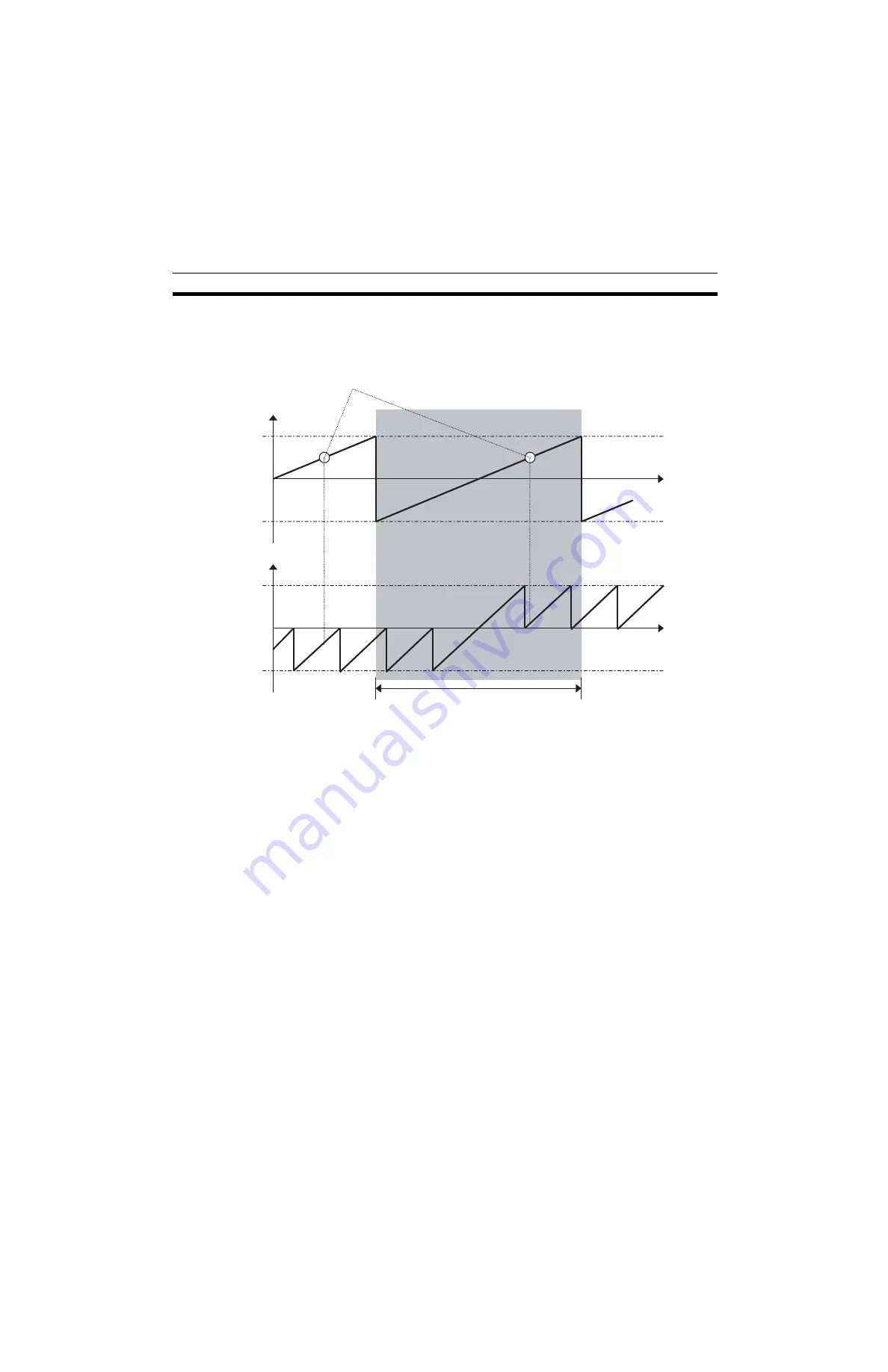
If the value other than 65535 is set in the servo parameter [Pn205: Multi-turn
limit setting], the multi-turn data will change as shown below:
0
−
32768
32767
0
Multi-turn data
Machine coordinate
system
The range that can be used normally
Within this range, the data from the absolute
encoder is unique. Thus, the present position is
constantly unique.
Rotation
amount
Rotation
amount
Summary of Contents for CS1W-MCH71 -
Page 2: ...CS1W MCH71 CJ1W MCH71 Motion Control Unit Operation Manual Revised June 2008 ...
Page 3: ...iv ...
Page 29: ...xxx ...
Page 33: ...xxxiv ...
Page 35: ...xxxvi ...
Page 39: ...xl ...
Page 69: ...24 Performance Section 1 7 ...
Page 99: ...54 Connecting MECHATROLINK Devices Section 3 5 ...
Page 283: ...238 Saving Data Section 5 4 ...
Page 417: ...372 Command Details Section 6 3 ...


