


297
Command Overview
Section 6-2
6-2-4
Program Number and Axis Declaration
The program number and axes to be used in the program are specified in
PROG command (Program Start). Refer to
Format
PROG_P <Program Number> Q <Axis Declaration>;
Program Number
The table below shows the relations between the program number and main
program/sub-program for motion tasks.
Axis Declaration
In "Axis Declaration", axes to be used in the program are specified with the bit
train (32-bit) in hexadecimal corresponding to the physical axis numbers.
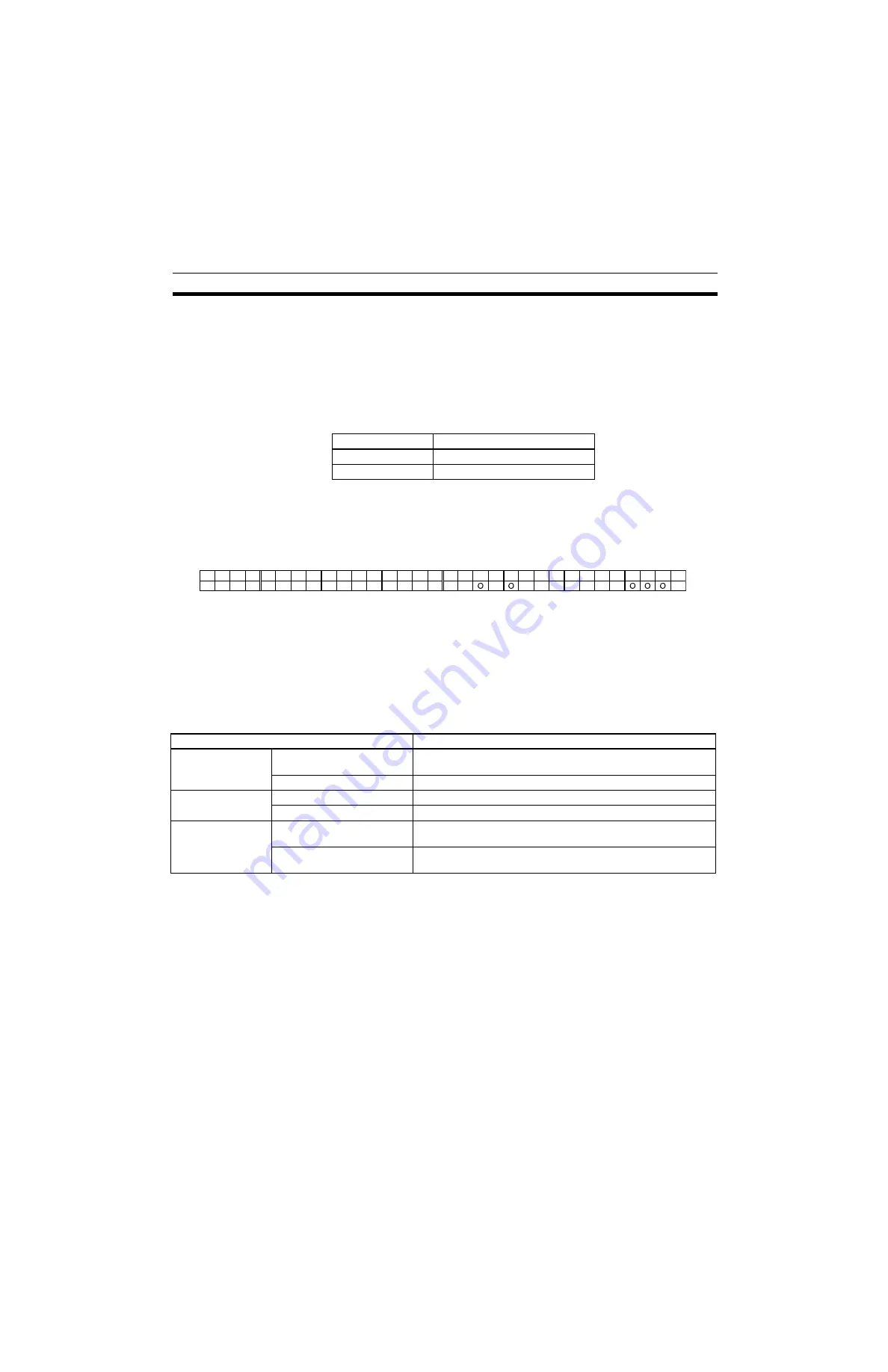
Program Example
When using the physical axes (numbers J02, J03, J04, J12, and J14) in the
motion task main program "0000", the bit train for the axes to be used will be
as shown below:
Therefore, in the PROG command, the following description is used:
PROG P000 Q0000280E;
6-2-5
Default Mode and Coordinate System
Various modes and coordinate systems can be used when executing com-
mands.
The following table shows the default settings for these.
Program No.
Program
0000-0499
Main program for motion tasks
0500-0999
Sub-program for motion tasks
J32 J31 J30 J29 J28 J27 J26 J25 J24 J23 J22 J21 J20 J19 J18 J17 J16 J15 J14 J13 J12 J11 J10 J09 J08 J07 J06 J05 J04 J03 J02 J01
0
0
0
0
2
8
0
E
↓
↓
↓
↓
↓
↓
↓
↓
Coordinate system
General description
Coordinate system
Machine coordinate system
Positioning is performed on the reference (machine) coordinate
system (Default setting)
Workpiece coordinate system Positioning is performed on the workpiece coordinate system.
Travel distance spec-
ification
Absolute specification
Positioning is performed with absolute positions. (Default setting)
Incremental specification
Positioning is performed with relative positions.
Operating mode
Stop Mode
For interpolation operations, the next operation is performed only
after positioning is completed. (Default setting)
Pass Mode
For interpolation operations, the next operation is performed with-
out waiting for positioning to be completed.
Summary of Contents for CS1W-MCH71 -
Page 2: ...CS1W MCH71 CJ1W MCH71 Motion Control Unit Operation Manual Revised June 2008 ...
Page 3: ...iv ...
Page 29: ...xxx ...
Page 33: ...xxxiv ...
Page 35: ...xxxvi ...
Page 39: ...xl ...
Page 69: ...24 Performance Section 1 7 ...
Page 99: ...54 Connecting MECHATROLINK Devices Section 3 5 ...
Page 283: ...238 Saving Data Section 5 4 ...
Page 417: ...372 Command Details Section 6 3 ...


