


A
B
C
D
E
F
G
H
L
M
N
P
Motore
Engine
sezione / section
N 9.3
175
999R
- M.Y. 2005 - edizione/edition 00
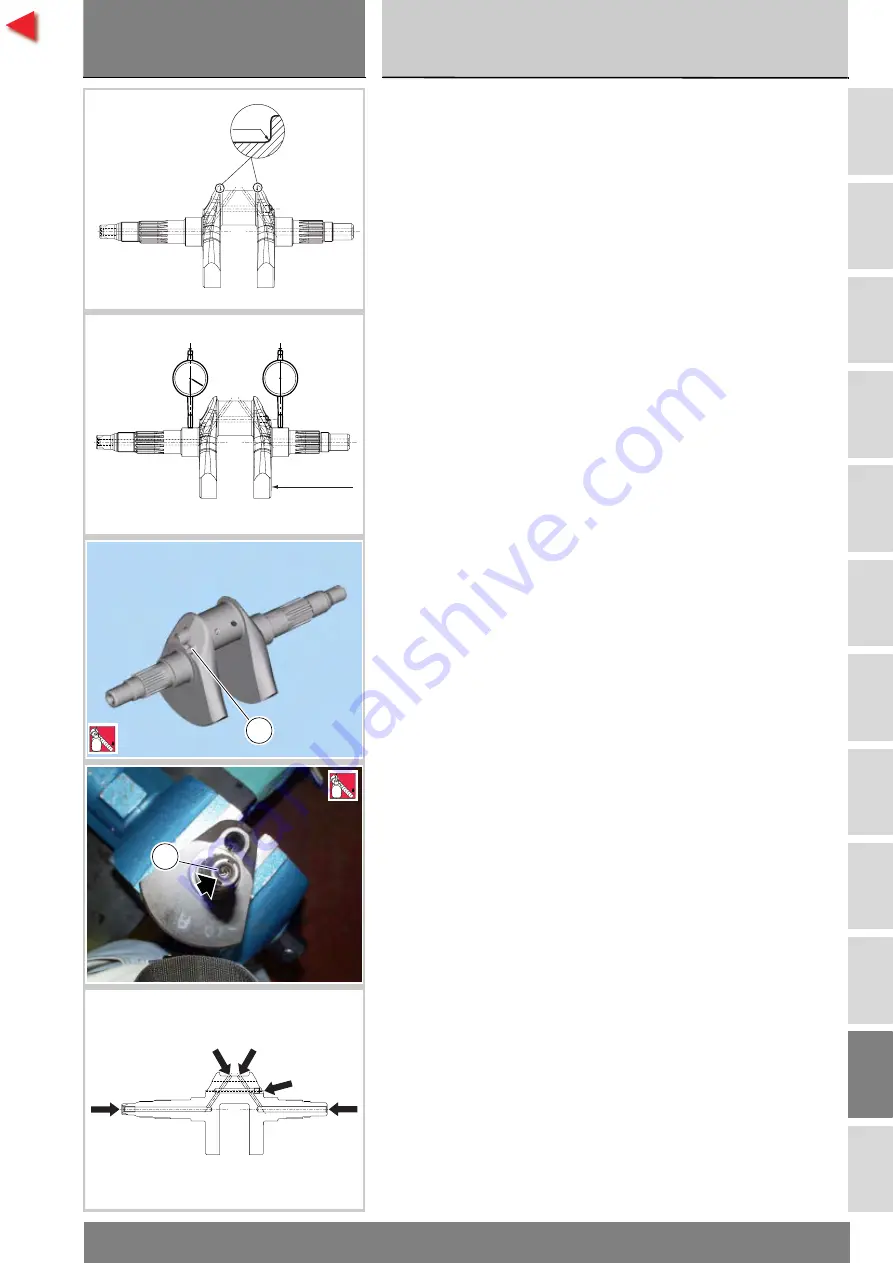
Verifica albero motore
I perni di banco e di biella non devono
presentare solchi o rigature;
le filettature, le sedi delle chiavette e
le scanalature devono essere in
buone condizioni.
Verificare che nella zona di raccordo
tra perno e spallamento non vi
siano segni di lavoro o bave.
Raggio di raccordo:
2
mm
(tolleranza
0 ÷ -0,25
mm).
Rilevare, con l'ausilio di un micrometro,
l'ovalizzazione e la conicità del perno di
biella eseguendo la misurazione in
diverse direzioni (Sez. C 1.1).
Rilevare, con l'ausilio del comparatore,
l'allineamento dei perni di banco
posizionando l'albero tra due
contropunte (Sez. C 1.1).
L'albero motore è fornito in due
selezioni (perno biella) punzonate
sul fianco mannaia, lato pignone.
Svitare tutti i grani filettati (4) e (8)
dall'albero motore; eventualmente
riscaldandolo per rimuovere il
bloccante applicato al montaggio.
Pulire tutte le canalizzazioni di
lubrificazione utilizzando spazzole
metalliche di diametro opportuno e
soffiando poi con aria compressa
per eliminari eventuali residui che
potrebbero limitare il passaggio dell'olio.
Mettere alcune gocce di frenafiletti
sia sulla filettatura dei grani (4) e (8) e
rimontare.
Serrare i grani (4) e (8) alle coppie
prescritte (Sez. C 3).
Checking the crankshaft
The main bearings and con-rod bearings
should not be scored or cracked;
the threads, keyways, and slots
must be in good condition.
Check for fretting or burs in the fillet
between crank pin and shoulder.
Fillet radius:
2
mm (tolerance
0-0.25
mm).
With the aid of a micrometer
measure out-of-round and taper
of the crank pin, making the
measurements in various different
directions (Sect. C 1.1).
Use a dial gauge to measure the
alignment of the main journals by
setting the crankshaft between two
opposing centres (Sect. C 1.1).
The crankshaft is supplied in two size
classes (crank pin), which are punched
on the flank on the pinion side.
Unscrew all the grub screws (4)
and (8) from the crankshaft, heating
the crankshaft, if necessary, to
remove the thread locker applied at
the time of assembly.
Clean all the oilways using suitable
diameter metal brushes and then
blowing in with compressed air to
remove any residues that may
have accumulated and that are
restricting the oil flow.
Apply a few drops of threadlocker to
the thread of grub screws (4) and (8),
and refit.
Tighten grub screws (4) and (8) to the
specified torque (Sect. C 3).
2 mm
0
-0,25
Punzonatura
Mark
4
5
LOCK
8
5
LOCK
Summary of Contents for 999R 2006
Page 11: ...A B C D E F G H L M N P Generalit 0 Description 0...
Page 25: ...A B C D E F G H L M N P Informazioni sul modello 0 Model specific information 0...
Page 29: ...A B C D E F G H L M N P Caratteristiche tecniche 0 Specifications 0...
Page 73: ...A B C D E F G H L M N P Uso e manutenzione 0 Use and Maintenance operations 0...
Page 150: ......
Page 151: ...A B C D E F G H L M N P Vestizione 0 Fairing 0...
Page 172: ......
Page 173: ...A B C D E F G H L M N P Comandi Dispositivi 0 Controls Devices 0...
Page 199: ...A B C D E F G H L M N P Ruote Sospensioni Freni0 Wheels Suspensions Brakes 0...
Page 246: ......
Page 247: ...A B C D E F G H L M N P Mototelaio 0 Frame 0...
Page 272: ......
Page 273: ...A B C D E F G H L M N P Impianto di alimentazione Scarico 0 Fuel system Exhaust system 0...
Page 305: ...A B C D E F G H L M N P Impianto iniezione accensione 0 Ignition injection system 1...
Page 330: ......
Page 331: ...A B C D E F G H L M N P Motore 0 Engine 1...
Page 510: ......
Page 511: ...A B C D E F G H L M N P Impianto elettrico 0 Electric system 0...
Page 596: ......
Page 597: ...A B C D E F G H L M N P Indice degli argomenti 0 Subject index 0...


