A
B
C
D
E
F
G
H
L
M
N
P
Uso e manutenzione
Use and Maintenance operations
sezione / section
D 4
31
999R Aggiornamento/Update
- M.Y. 2006 - edizione/edition 00
Operate the brake lever repeatedly so
that the pads are firmly bedded in
against the disc by the force of the
brake fluid.
Check that the brake fluid level in
the master cylinder reservoir is above
the
MIN
mark. If necessary, top up
as follows. Turn the handlebar so that
the reservoir is level.
Unscrew the three screws (4) and
remove the reservoir cover.
Remove the inner membrane from
the reservoir. Top up to MAX level
with the specified brake fluid.
Refit all previously removed
components.
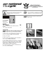
Changing the rear brake pads
Check through the slot between the
two calliper halves that there is at
least
1
mm of friction material on
the pads.
Important
If either of the pads is worn,
both pads must be renewed as a set.
Change the brake pads as follows:
Withdraw the brake pad retaining
pin (7) from the outside.
Remove the clip (5) from between the
two calliper halves.
Force the calliper pistons back into
their bores by forcing the old brake
pads apart.
Remove the worn pads.
Notes
Change pads that have a shiny
or “vitrified” appearance.
Insert the new pads and clip (5).
Insert the retaining pin (7) and drive
it home.
Operate the brake pedal repeatedly so
that the pads are bedded in against
the disc by the force of the brake fluid.
Check that the brake fluid level in the
master cylinder reservoir is between
the
MIN
and
MAX
marks. If not,
unscrew the reservoir cover (6) and
top up with the recommended brake
fluid.
Azionare ripetutamente la leva del
freno per permettere l’assestamento
delle pastiglie sotto l’azione di spinta
del liquido freni.
Verificare che il livello nel serbatoio
della pompa non sia al di sotto della
tacca di
MIN
. In caso contrario
provvedere al rabbocco procedendo
come segue. Ruotare il semimanubrio
per livellare il serbatoio.
Rimuovere il coperchio del serbatoio
svitando le tre viti (4).
Rimuovere la membrana interna dal
serbatoio. Rabboccare con liquido
prescritto fino al livello massimo.
Rimontare i componenti rimossi.
Sostituzione pastiglie freno
posteriore
Controllare attraverso la fessura
ricavata tra le due semipinze che
risulti visibile almeno
1
mm di
materiale di attrito sulle pastiglie.
Importante
Se anche una sola delle
pastiglie risulta consumata sarà
necessario sostituirle entrambe.
Procedere alla sostituzione delle
pastiglie in questo modo:
Sfilare il perno (7) di tenuta pastiglie
verso l’esterno.
Rimuovere la molla (5) di tenuta
pastiglie posta tra le semipinze.
Spingere i pistoncini della pinza
completamente dentro ai propri
alloggiamenti, divaricando le pastiglie
usate.
Sfilare le pastiglie usurate.
Note
Sostituire le pastiglie che
presentano un aspetto lucido o
“vetroso”.
Inserire le pastiglie nuove e relativa
molla (5).
Infilare il perno di centraggio (7) e
spingerlo fino in battuta.
Azionare ripetutamente il pedale del
freno per permettere l’assestamento
delle pastiglie sotto l’azione di spinta
del liquido freni.
Verificare che il livello nel serbatoio
risulti compreso tra le tacche di
MIN
e
di
MAX
. In caso contrario provvedere
al rabbocco dopo aver svitato il
tappo (6) del serbatoio.
MIN
4
1 mm
5
7
MAX
MIN
6
Summary of Contents for 999R 2006
Page 11: ...A B C D E F G H L M N P Generalit 0 Description 0...
Page 25: ...A B C D E F G H L M N P Informazioni sul modello 0 Model specific information 0...
Page 29: ...A B C D E F G H L M N P Caratteristiche tecniche 0 Specifications 0...
Page 73: ...A B C D E F G H L M N P Uso e manutenzione 0 Use and Maintenance operations 0...
Page 150: ......
Page 151: ...A B C D E F G H L M N P Vestizione 0 Fairing 0...
Page 172: ......
Page 173: ...A B C D E F G H L M N P Comandi Dispositivi 0 Controls Devices 0...
Page 199: ...A B C D E F G H L M N P Ruote Sospensioni Freni0 Wheels Suspensions Brakes 0...
Page 246: ......
Page 247: ...A B C D E F G H L M N P Mototelaio 0 Frame 0...
Page 272: ......
Page 273: ...A B C D E F G H L M N P Impianto di alimentazione Scarico 0 Fuel system Exhaust system 0...
Page 305: ...A B C D E F G H L M N P Impianto iniezione accensione 0 Ignition injection system 1...
Page 330: ......
Page 331: ...A B C D E F G H L M N P Motore 0 Engine 1...
Page 510: ......
Page 511: ...A B C D E F G H L M N P Impianto elettrico 0 Electric system 0...
Page 596: ......
Page 597: ...A B C D E F G H L M N P Indice degli argomenti 0 Subject index 0...