Installing the Hardware
Step 5: Installing the Voice and Fax Board(s) in the PC
Octel 50 Installation Guide
3-9
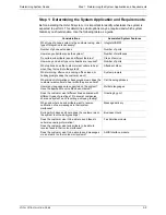
Setting the TR112 Board’s Hardware Interrupt Level
The hardware interrupt allows the board to communicate with the driver, which in turn
communicates with the Octel 50 system. The J32 or J33 jumper controls the TR112
board’s hardware interrupt level, depending on the interrupt you select. J32 controls
interrupts 2 through 7. J33 controls interrupts 10, 11, 12, 14, and 15. Use the same
interrupt level for all Brooktrout boards you install in the Octel 50 PC.
For the TR112 board, the default interrupt level of 10 should be acceptable in most cases.
Interrupt 10 is set on the J33 jumper.
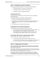
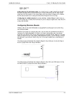
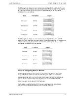
Setting the TR112 Board’s DMA Channel
The DMA Channel transfers data from the TR112 board to the PC. The J31 jumper block
controls the DMA Channel for the TR112 board. Channel 1 is the recommended setting.
On the first TR112 board, you must set two jumpers—both jumpers must be set to the
same channel. On the remaining TR112 boards, you only need to set one jumper.
Step 5: Installing the Voice and Fax Board(s) in the PC
Use caution when handling voice and fax boards as they are electrostatic-sensitive. Make
sure you ground the PC, the work area, and the ground end of the antistatic wrist strap
prior to handling a board, and always use antistatic wrist straps and
electrostatic-dissipative mats while handling a board.
To install the voice and fax boards:
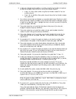
1. Turn off the power to the PC and any peripherals.
2. Unfasten the screws retaining the PC’s cover and remove the cover.
3. Select an expansion slot in which to install the board. Use an 8- or 16-bit slot (PCI,
ISA) for the Dialogic and Rhetorex voice boards. Use a 16-bit slot for the Brooktrout
fax boards.
4. Unfasten the screw retaining the slot cover, located at the rear of the PC chassis, and
remove the slot cover.
5. Insert the board into the expansion slot by holding the board at the top of each corner.
Apply equal pressure to both sides of the board and push down firmly to seat the
board. The board should easily slide down most of the way. If you feel any resistance,
check the alignment of the board.
6. Make sure that the board’s RJ-11 or RJ-14 jacks are accessible from the rear of the
PC chassis.
7. Secure the board’s metal bracket with the retaining screw.
8. Replace the PC’s cover, and fasten it back into place with the retaining screws.
Содержание Octel 50
Страница 2: ......
Страница 3: ...Octel 50 Installation Guide 585 313 134 Comcode 108503004 101 1840 000 Issue 1 June 1999 ...
Страница 8: ......
Страница 22: ...Determining System Needs Step 3 Consider Additional Hardware Needs OCTEL 50 INSTALLATION GUIDE 2 6 Notes ...
Страница 36: ...Installing the Hardware Step 10 Installing the Sentinel Octel 50 Installation Guide 3 14 Notes ...
Страница 52: ...Running the SMDI Utility Running SMDI as a Standalone Utility Octel 50 Installation Guide 5 4 Notes ...
Страница 180: ...Integrating with an Uninterruptible Power Supply Running UPS Integration Octel 50 Installation Guide 10 4 Notes ...


