14 - 37
MELSEC-A
14 TROUBLESHOOTING
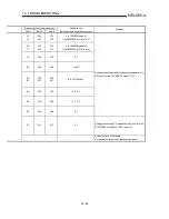
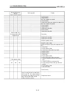
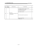
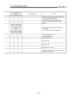
Relevant buffer memory
address
Axis 1
Axis 2
Axis 3
Checking method
Remedy
1. Check the speed command (pulse train
frequency).
2. Check if the motor speed determined by the
set speed of the AD75 has exceeded the
rated speed of the servomotor.
Set the speed correctly. (600kpps or less)
1. Increase acceleration/deceleration time
constant.
2. Reduce the speed.
Reconsider the acceleration/deceleration time constant.
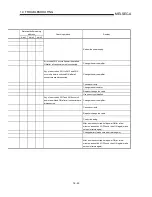
112
262
412
1. Adjust the servo gain.
2. Check " Pr.112 Load inertia ratio" (load
inertia moment ratio).
3. Increase the acceleration/deceleration time
constant.
4. Reduce the speed.
1. Re-set servo gain to proper value.
2. If setting cannot be made by the servo gain:
1) Reduce " Pr.112 Load inertia ratio" (load inertia
moment ratio); or
2) Reexamine the acceleration/deceleration time
constant.
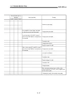
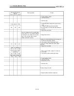
Motor type
103 253 403
Motor speed
105 255 405
Check the servo parameters " Pr.103 Motor
type" and " Pr.105 Motor speed".
Set correctly.
1. Change the cable.
2. Change the servomotor.
Change the cable.
Change the servomotor.
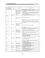
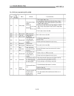
Check if the U, V, W cables have been
connected using a tester.
Correct the wiring.
Measure the resistance across transistor
module terminals using a tester.
Change the transistor module or unit.
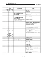
1. Check across terminal block U, V, W
phases and case using a tester.
2. Check across servomotor U, V, W phases
and core using a tester and megger.
Correct the ground fault.
Change the unit or servomotor.
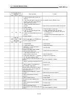
Check if the relay or valve has operated in the
periphery.
Take noise suppression measures.
Check the connection across terminal block C-
P.
Connect correctly.
Check the resistance of the regenerative
power transistor using a tester.
Change the unit.
Measure across terminal block C-P using a
tester (measure about 3 minutes after the
charge lamp goes OFF).
Change the unit.
Measure the input voltage (R, S, T) with a
voltmeter.
Reconsider the power supply capacity.
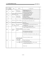
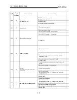
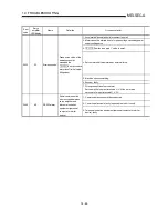
Check for disconnection of the cable
connector.
Connect correctly.
Check for an open cable, etc.
Change the cable.
The relay or valve has operated in the
periphery.
Take noise suppression measures.
Check for disconnection of the terminal
connector.
Connect correctly.
Check if the input pulse is faulty.
Change the AD75.
Check if the relay or valve has operated in the
periphery.
Take noise suppression measures.
Summary of Contents for A1SD75M1
Page 2: ......
Page 20: ...A 18 MEMO...
Page 22: ...MEMO...
Page 27: ...1 5 MELSEC A 1 PRODUCT OUTLINE MEMO...
Page 42: ...1 20 MELSEC A 1 PRODUCT OUTLINE MEMO...
Page 52: ...2 10 MELSEC A 2 SYSTEM CONFIGURATION MEMO...
Page 111: ...5 21 MELSEC A 5 DATA USED FOR POSITIONING CONTROL MEMO...
Page 115: ...5 25 MELSEC A 5 DATA USED FOR POSITIONING CONTROL MEMO...
Page 123: ...5 33 MELSEC A 5 DATA USED FOR POSITIONING CONTROL MEMO...
Page 127: ...5 37 MELSEC A 5 DATA USED FOR POSITIONING CONTROL MEMO...
Page 167: ...5 77 MELSEC A 5 DATA USED FOR POSITIONING CONTROL MEMO...
Page 193: ...5 103 MELSEC A 5 DATA USED FOR POSITIONING CONTROL MEMO...
Page 276: ...5 186 MELSEC A 5 DATA USED FOR POSITIONING CONTROL MEMO...
Page 332: ...7 18 MELSEC A 7 MEMORY CONFIGURATION AND DATA PROCESS MEMO...
Page 334: ...MEMO...
Page 422: ...9 64 MELSEC A 9 MAIN POSITIONING CONTROL MEMO...
Page 446: ...10 24 MELSEC A 10 ADVANCED POSITIONING CONTROL MEMO...
Page 472: ...11 26 MELSEC A 11 MANUAL CONTROL MEMO...
Page 576: ...12 104 MELSEC A 12 CONTROL AUXILIARY FUNCTIONS MEMO...
Page 745: ......


