9 - 20
MELSEC-A
9 MAIN POSITIONING CONTROL
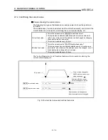
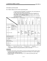
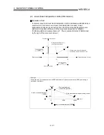
Starting the interpolation control
The positioning data Nos. of the reference axis (axis in which interpolation control
was set in " Da.2 Control method") are started when starting the interpolation
control. (Starting of the interpolation axis is not required.)
The following errors will occur and the positioning will not start if both reference
axis and the interpolation axis are started.
•
Reference axis
: Interpolation while target axis BUSY (error code: 519)
•
Interpolation axis : Control method setting error (error code: 524), start during
operation (warning code: 100).
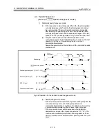
Interpolation control continuous positioning
When carrying out interpolation control in which "continuous positioning control"
and "continuous path control" are designated in the operation pattern, the
positioning method for all positioning data from the started positioning data to the
positioning data in which "positioning complete" is set must be set to interpolation
control.
The AD75 may malfunction if a control method other than interpolation control is
set.
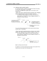
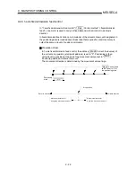
The path pattern can be selected when carrying out "continuous path control"
using interpolation control. (Select either the "positioning address mode" or the
"near pass mode" is selected. Refer to section "12.3.3 Near pass mode function"
for details.)
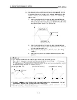
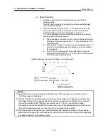
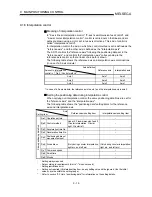
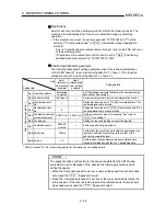
Speed during interpolation control
Either the "composite speed" or "reference axis speed" can be designated as the
speed during interpolation control.
(Set in " Pr.21 Interpolation speed designation method".)
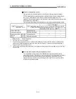
POINT
The speed limit does not function for the speed calculated by the AD75 during
interpolation control. Because of this, observe the following precautions when
setting the speed.
•
When the "composite speed" is set, set a value so the speed for each axis does
not exceed the " Pr.7 Speed limit value".
•
When the "reference axis speed" is set, set so the major axis side becomes the
reference axis. If the minor axis side is set as the reference axis, the major axis
side speed may exceed the " Pr.7 Speed limit value".
Summary of Contents for A1SD75M1
Page 2: ......
Page 20: ...A 18 MEMO...
Page 22: ...MEMO...
Page 27: ...1 5 MELSEC A 1 PRODUCT OUTLINE MEMO...
Page 42: ...1 20 MELSEC A 1 PRODUCT OUTLINE MEMO...
Page 52: ...2 10 MELSEC A 2 SYSTEM CONFIGURATION MEMO...
Page 111: ...5 21 MELSEC A 5 DATA USED FOR POSITIONING CONTROL MEMO...
Page 115: ...5 25 MELSEC A 5 DATA USED FOR POSITIONING CONTROL MEMO...
Page 123: ...5 33 MELSEC A 5 DATA USED FOR POSITIONING CONTROL MEMO...
Page 127: ...5 37 MELSEC A 5 DATA USED FOR POSITIONING CONTROL MEMO...
Page 167: ...5 77 MELSEC A 5 DATA USED FOR POSITIONING CONTROL MEMO...
Page 193: ...5 103 MELSEC A 5 DATA USED FOR POSITIONING CONTROL MEMO...
Page 276: ...5 186 MELSEC A 5 DATA USED FOR POSITIONING CONTROL MEMO...
Page 332: ...7 18 MELSEC A 7 MEMORY CONFIGURATION AND DATA PROCESS MEMO...
Page 334: ...MEMO...
Page 422: ...9 64 MELSEC A 9 MAIN POSITIONING CONTROL MEMO...
Page 446: ...10 24 MELSEC A 10 ADVANCED POSITIONING CONTROL MEMO...
Page 472: ...11 26 MELSEC A 11 MANUAL CONTROL MEMO...
Page 576: ...12 104 MELSEC A 12 CONTROL AUXILIARY FUNCTIONS MEMO...
Page 745: ......


