9 - 21
MELSEC-A
9 MAIN POSITIONING CONTROL
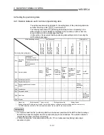
Limits to interpolation control
There are limits to the interpolation control that can be executed and speed
( Pr.21 Interpolation speed designation method) that can be set, depending on
the " Pr.1 Unit setting" of the reference axis and interpolation axis. (For
example, circular interpolation control cannot be executed if the reference axis and
interpolation axis units differ.)
The following table shows the interpolation control and speed designation limits.
Pr.1 Unit setting *
1
"
Da.2 Control method"
interpolation control
Pr.21 Interpolation speed
designation method
Reference axis and interpolation
axis units are the same, or a
combination of "mm" and "inch".
Reference axis and
interpolation axis units
differ *
3
Composite speed
Linear 2 (ABS, INC)
Fixed-dimension feed 2
Reference axis speed
Composite speed
*
2
Circular interpolation (ABS, INC)
Right arc
(ABS, INC)
Left arc
(ABS, INC) Reference axis speed
: Setting possible, : Setting not possible.
*
1
"mm" and "inch" unit mix possible.
*
2
"degree" setting not possible. An error "control method setting error" (error code: 524) will occur and the position
cannot start if circular interpolation control is set when the unit is "degree". The machine will immediately stop if
"degree" is set during positioning control.
*
3
The unit set in the reference axis will be used for the speed unit during control if the units differ or if "mm" and "inch"
are combined.
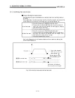
Axis operation status during interpolation control
"In interpolation" will be stored in the " Md.35 Axis operation status" during
interpolation control. "Standing by" will be stored when the interpolation operation
is terminated. Both the reference axis and interpolation axis will carry out a
deceleration stop if an error occurs during control, and "error occurring" will be
stored in the operation status.
Summary of Contents for A1SD75M1
Page 2: ......
Page 20: ...A 18 MEMO...
Page 22: ...MEMO...
Page 27: ...1 5 MELSEC A 1 PRODUCT OUTLINE MEMO...
Page 42: ...1 20 MELSEC A 1 PRODUCT OUTLINE MEMO...
Page 52: ...2 10 MELSEC A 2 SYSTEM CONFIGURATION MEMO...
Page 111: ...5 21 MELSEC A 5 DATA USED FOR POSITIONING CONTROL MEMO...
Page 115: ...5 25 MELSEC A 5 DATA USED FOR POSITIONING CONTROL MEMO...
Page 123: ...5 33 MELSEC A 5 DATA USED FOR POSITIONING CONTROL MEMO...
Page 127: ...5 37 MELSEC A 5 DATA USED FOR POSITIONING CONTROL MEMO...
Page 167: ...5 77 MELSEC A 5 DATA USED FOR POSITIONING CONTROL MEMO...
Page 193: ...5 103 MELSEC A 5 DATA USED FOR POSITIONING CONTROL MEMO...
Page 276: ...5 186 MELSEC A 5 DATA USED FOR POSITIONING CONTROL MEMO...
Page 332: ...7 18 MELSEC A 7 MEMORY CONFIGURATION AND DATA PROCESS MEMO...
Page 334: ...MEMO...
Page 422: ...9 64 MELSEC A 9 MAIN POSITIONING CONTROL MEMO...
Page 446: ...10 24 MELSEC A 10 ADVANCED POSITIONING CONTROL MEMO...
Page 472: ...11 26 MELSEC A 11 MANUAL CONTROL MEMO...
Page 576: ...12 104 MELSEC A 12 CONTROL AUXILIARY FUNCTIONS MEMO...
Page 745: ......


