Appendix - 46
MELSEC-A
APPENDICES
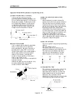
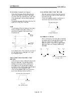
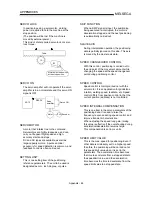
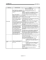
SUDDEN STOP
A stop carried out in a shorter time than the
deceleration time designated in the
parameters.
Full speed
Sudden stop
Time
Deceleration time
TEACHING
When the positioning address is uncertain, or
gauging is required, this function is used by
the manual operation to search for and teach
the position to the machine.
For example, complex addresses such as
drawings can be taught by tracing a model,
and the positioning operation can be
reproduced.
TEACHING UNIT
This is a device capable of writing, reading,
running, and monitoring data.
It is used connected to the AD75. The model is
AD75TU.
TORQUE CONTROL
In this function, a limit is established for the
resistance torque applied to the servomotor.
The power is turned OFF if torque exceeding
that value is applied to the motor.
When excessive torque is applied to a motor, it
causes the current to suddenly increase. Motor
burning and other stress on the motor occurs,
and the life of the motor is shortened.
This function utilizes the sudden increase in
the torque when the machine returns to the
zero point to issue a command to stop the
motor.
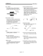
TORQUE LOOP MODE
Also called the current loop mode.
Refer to "POSITIONING LOOP MODE".
TORQUE RIPPLE
Torque width variations, deviations in the
torque.
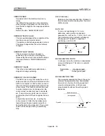
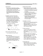
TURNTABLE
A rotating table, which is turned using power.
The table is used divided from one 360°
rotation into the required locations for work.
The positioning control unit is "degree".
Rotated by the motor
30°
UNIT SETTING
This is the setting of the unit for the actual
address to which positioning is required, or for
the movement amount.
The following units can be set: mm, inch,
degree and pulse. The initial value in the
parameters is a pulse unit.
WARNING
A warning is output as a warning code in when
an abnormality is detected that is not serious
enough to require cancellation or stoppage of
the positioning operation. Warnings are
handled differently than errors.
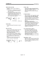
WITH MODE
This is the mode that outputs the M code
before the start of the positioning. This mode
turns ON at the positioning start, enabling
voltage to be applied to the welding
electrodes, display of positioning speeds, etc.
Refer to the term "AFTER MODE".
Summary of Contents for A1SD75M1
Page 2: ......
Page 20: ...A 18 MEMO...
Page 22: ...MEMO...
Page 27: ...1 5 MELSEC A 1 PRODUCT OUTLINE MEMO...
Page 42: ...1 20 MELSEC A 1 PRODUCT OUTLINE MEMO...
Page 52: ...2 10 MELSEC A 2 SYSTEM CONFIGURATION MEMO...
Page 111: ...5 21 MELSEC A 5 DATA USED FOR POSITIONING CONTROL MEMO...
Page 115: ...5 25 MELSEC A 5 DATA USED FOR POSITIONING CONTROL MEMO...
Page 123: ...5 33 MELSEC A 5 DATA USED FOR POSITIONING CONTROL MEMO...
Page 127: ...5 37 MELSEC A 5 DATA USED FOR POSITIONING CONTROL MEMO...
Page 167: ...5 77 MELSEC A 5 DATA USED FOR POSITIONING CONTROL MEMO...
Page 193: ...5 103 MELSEC A 5 DATA USED FOR POSITIONING CONTROL MEMO...
Page 276: ...5 186 MELSEC A 5 DATA USED FOR POSITIONING CONTROL MEMO...
Page 332: ...7 18 MELSEC A 7 MEMORY CONFIGURATION AND DATA PROCESS MEMO...
Page 334: ...MEMO...
Page 422: ...9 64 MELSEC A 9 MAIN POSITIONING CONTROL MEMO...
Page 446: ...10 24 MELSEC A 10 ADVANCED POSITIONING CONTROL MEMO...
Page 472: ...11 26 MELSEC A 11 MANUAL CONTROL MEMO...
Page 576: ...12 104 MELSEC A 12 CONTROL AUXILIARY FUNCTIONS MEMO...
Page 745: ......

