7 - 7
MELSEC-A
7 MEMORY CONFIGURATION AND DATA PROCESS
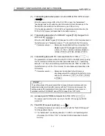
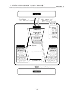
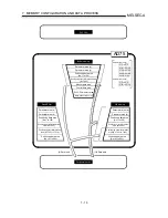
(1) Transmitting data when power is turned ON or PLC CPU is reset
(
)
When the power is turned ON or the PLC CPU is reset, the "parameters",
"positioning data" and "positioning start information" stored (backed up) in the
flash ROM is transmitted to the buffer memory and OS memory.
(The "positioning data (No. 101 to 600)" and "positioning start information (No.
7001 to 7010)" data is not transmitted to the buffer memory.)
(2) Transmitting data when PLC READY signal [Y1D] changes from
OFF to ON (
)
When the PLC READY signal [Y1D] changes from OFF to ON, the data stored in
the buffer memory's "parameter area (a) *1" is transmitted to the OS memory.
*
1
Parameter area (a) ....... Parameters transmitted to OS memory when PLC
READY signal [Y1D] changes from OFF to ON
( Pr.1 to
Pr.4 , Pr.10 to Pr.25 , Pr.45 to
Pr.59 , Pr.100 to Pr.138 , Pr.149 , Pr.150 )
(3) Transmitting data with TO command from PLC CPU (
)
The parameters or data is written from the PLC CPU to the buffer memory using
the TO command. At this time, when the "parameter area (b) *2", "positioning
data (No. 1 to 100)" and "positioning start information (No. 7000)" is written into
the buffer memory with the TO command, it is simultaneously transmitted to the
OS memory.
*
2
Parameter area (b) ....... Parameters transmitted to the OS memory
simultaneously with the writing to the buffer memory
with the TO command. ( Pr.7 to Pr.9 , Pr.26
to Pr.44 )
POINT
The setting values of the parameters that correspond to parameter area (b) are
valid when written into the buffer memory with the TO command. However, the
setting values of the parameters that correspond to parameter area (a) are not
validated until the PLC READY signal [Y1D] changes from OFF to ON.
(4) Accessing with FROM command from PLC CPU (
)
The data is read from the buffer memory to the PLC CPU using the FROM
command.
(5) Flash ROM request (reading) (
)
The following transmission process is carried out with the "flash ROM request"
from the peripheral device.
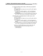
1) The "parameters", "positioning data (No. 1 to 600)", and "positioning start
information (No. 7000 to 7010)" in the flash ROM is transmitted to the OS
memory.
Summary of Contents for A1SD75M1
Page 2: ......
Page 20: ...A 18 MEMO...
Page 22: ...MEMO...
Page 27: ...1 5 MELSEC A 1 PRODUCT OUTLINE MEMO...
Page 42: ...1 20 MELSEC A 1 PRODUCT OUTLINE MEMO...
Page 52: ...2 10 MELSEC A 2 SYSTEM CONFIGURATION MEMO...
Page 111: ...5 21 MELSEC A 5 DATA USED FOR POSITIONING CONTROL MEMO...
Page 115: ...5 25 MELSEC A 5 DATA USED FOR POSITIONING CONTROL MEMO...
Page 123: ...5 33 MELSEC A 5 DATA USED FOR POSITIONING CONTROL MEMO...
Page 127: ...5 37 MELSEC A 5 DATA USED FOR POSITIONING CONTROL MEMO...
Page 167: ...5 77 MELSEC A 5 DATA USED FOR POSITIONING CONTROL MEMO...
Page 193: ...5 103 MELSEC A 5 DATA USED FOR POSITIONING CONTROL MEMO...
Page 276: ...5 186 MELSEC A 5 DATA USED FOR POSITIONING CONTROL MEMO...
Page 332: ...7 18 MELSEC A 7 MEMORY CONFIGURATION AND DATA PROCESS MEMO...
Page 334: ...MEMO...
Page 422: ...9 64 MELSEC A 9 MAIN POSITIONING CONTROL MEMO...
Page 446: ...10 24 MELSEC A 10 ADVANCED POSITIONING CONTROL MEMO...
Page 472: ...11 26 MELSEC A 11 MANUAL CONTROL MEMO...
Page 576: ...12 104 MELSEC A 12 CONTROL AUXILIARY FUNCTIONS MEMO...
Page 745: ......

