9 - 46
MELSEC-A
9 MAIN POSITIONING CONTROL
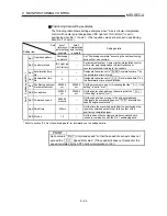
Positioning data setting examples
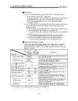
The following table shows setting examples when "2-axis circular interpolation
control with center point designation (INC right arc, INC left arc)" is set in
positioning data No. 1 of axis 1. (The required values are also set in positioning
data No. 1 of axis 2.)
Axis
Setting item
Axis 1
(reference
axis) setting
example
Axis 2
(interpolation
axis) setting
example
Setting details
Da.1
Operation pattern
Positioning
complete
–
Set "Positioning complete" assuming the next positioning
data will not be executed.
Da.2
Control method
INC right arc
INC left arc
–
Set increment system, 2-axis circular interpolation control
with center point designation. (Select clockwise or
counterclockwise according to the control.)
Da.3
Acceleration time
No.
1 –
Designate the value set in "
Pr.26 Acceleration time 1" as
the acceleration time at start.
Da.4
Deceleration time
No.
0 –
Designate the value set in "
Pr.9 Deceleration time 0" as
the deceleration time at deceleration.
Da.5
Positioning address/
movement amount
80000.0
µ
m
60000.0
µ
m
Set the movement amount. (Assuming that the "
Pr.1 Unit
setting" is set to "mm".)
Da.6
Arc address
40000.0
µ
m
30000.0
µ
m
Set the center point address. (Assuming that the "
Pr.1
Unit setting" is set to "mm".)
Da.7
Command speed
6000.00
mm/min
–
Set the speed when moving to the end point address.
(Designate the composite speed in "
Pr.21 Interpolation
speed designation method".)
Da.8
Dwell time
500ms
–
Set the time the machine dwells after the positioning stop
(position command output stop) to the output of the
positioning complete signal.
Ax
is 1 Positioning data N
o
. 1
Da.9
M code
10
–
Set this when other auxiliary operation commands are
issued in combination with the No. 1 positioning data.
* Refer to section "5.3 List of positioning data" for information on the setting details.
POINT
Set a value in " Da.7 Command speed" so that the speed of each axis does not
exceed the " Pr.7 Speed limit value". (The speed limit does not function for the
speed calculated by the AD75 during interpolation control.)
Summary of Contents for A1SD75M1
Page 2: ......
Page 20: ...A 18 MEMO...
Page 22: ...MEMO...
Page 27: ...1 5 MELSEC A 1 PRODUCT OUTLINE MEMO...
Page 42: ...1 20 MELSEC A 1 PRODUCT OUTLINE MEMO...
Page 52: ...2 10 MELSEC A 2 SYSTEM CONFIGURATION MEMO...
Page 111: ...5 21 MELSEC A 5 DATA USED FOR POSITIONING CONTROL MEMO...
Page 115: ...5 25 MELSEC A 5 DATA USED FOR POSITIONING CONTROL MEMO...
Page 123: ...5 33 MELSEC A 5 DATA USED FOR POSITIONING CONTROL MEMO...
Page 127: ...5 37 MELSEC A 5 DATA USED FOR POSITIONING CONTROL MEMO...
Page 167: ...5 77 MELSEC A 5 DATA USED FOR POSITIONING CONTROL MEMO...
Page 193: ...5 103 MELSEC A 5 DATA USED FOR POSITIONING CONTROL MEMO...
Page 276: ...5 186 MELSEC A 5 DATA USED FOR POSITIONING CONTROL MEMO...
Page 332: ...7 18 MELSEC A 7 MEMORY CONFIGURATION AND DATA PROCESS MEMO...
Page 334: ...MEMO...
Page 422: ...9 64 MELSEC A 9 MAIN POSITIONING CONTROL MEMO...
Page 446: ...10 24 MELSEC A 10 ADVANCED POSITIONING CONTROL MEMO...
Page 472: ...11 26 MELSEC A 11 MANUAL CONTROL MEMO...
Page 576: ...12 104 MELSEC A 12 CONTROL AUXILIARY FUNCTIONS MEMO...
Page 745: ......


