14 - 1
14
Chapter 14
TROUBLESHOOTING
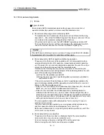
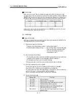
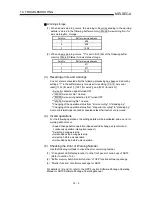
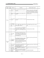
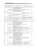
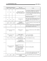
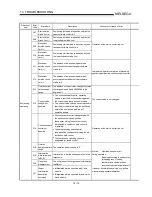
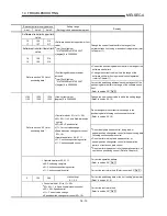
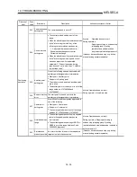
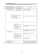
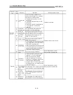
The "errors" and "warnings" detected by the AD75 and servo amplifier are explained in
this chapter.
Errors and warnings can be confirmed with the AD75 LED display and peripheral devices.
When an "error" or "warning" is detected, confirm the detection details and carry out the
required measures.
14.1 Error and warning details.........................................................................................14- 2
14.2 List of errors .............................................................................................................14- 6
14.2.1 Errors detected by AD75 ...........................................................................14- 6
14.2.2 Errors detected by MR-H-B (MR-H-BN)...................................................14- 26
14.2.3 Errors detected by MR-J-B .......................................................................14- 34
14.2.4 Errors detected by MR-J2-B .....................................................................14- 42
14.2.5 Errors detected by MR-J2S-B...................................................................14- 50
14.2.6 Errors detected by MR-J2-03B5 ...............................................................14- 58
14.3 List
of
warnings .......................................................................................................14- 64
14.3.1 Warnings detected by AD75.....................................................................14- 64
14.3.2 Warnings detected by MR-H-B (MR-H-BN) .............................................14- 70
14.3.3 Warnings detected by MR-J-B..................................................................14- 72
14.3.4 Warnings detected by MR-J2-B................................................................14- 74
14.3.5 Warnings detected by MR-J2S-B .............................................................14- 76
14.3.6 Warnings detected by MR-J2-03B5 .........................................................14- 78
14.4 Start during error history.........................................................................................14- 80
Summary of Contents for A1SD75M1
Page 2: ......
Page 20: ...A 18 MEMO...
Page 22: ...MEMO...
Page 27: ...1 5 MELSEC A 1 PRODUCT OUTLINE MEMO...
Page 42: ...1 20 MELSEC A 1 PRODUCT OUTLINE MEMO...
Page 52: ...2 10 MELSEC A 2 SYSTEM CONFIGURATION MEMO...
Page 111: ...5 21 MELSEC A 5 DATA USED FOR POSITIONING CONTROL MEMO...
Page 115: ...5 25 MELSEC A 5 DATA USED FOR POSITIONING CONTROL MEMO...
Page 123: ...5 33 MELSEC A 5 DATA USED FOR POSITIONING CONTROL MEMO...
Page 127: ...5 37 MELSEC A 5 DATA USED FOR POSITIONING CONTROL MEMO...
Page 167: ...5 77 MELSEC A 5 DATA USED FOR POSITIONING CONTROL MEMO...
Page 193: ...5 103 MELSEC A 5 DATA USED FOR POSITIONING CONTROL MEMO...
Page 276: ...5 186 MELSEC A 5 DATA USED FOR POSITIONING CONTROL MEMO...
Page 332: ...7 18 MELSEC A 7 MEMORY CONFIGURATION AND DATA PROCESS MEMO...
Page 334: ...MEMO...
Page 422: ...9 64 MELSEC A 9 MAIN POSITIONING CONTROL MEMO...
Page 446: ...10 24 MELSEC A 10 ADVANCED POSITIONING CONTROL MEMO...
Page 472: ...11 26 MELSEC A 11 MANUAL CONTROL MEMO...
Page 576: ...12 104 MELSEC A 12 CONTROL AUXILIARY FUNCTIONS MEMO...
Page 745: ......

