2 - 4
MELSEC-A
2 SYSTEM CONFIGURATION
2.2 List of configuration devices
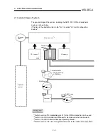
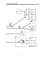
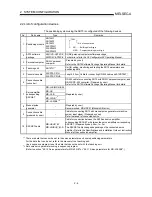
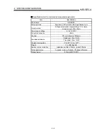
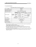
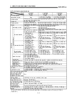
The positioning system using the AD75 is configured of the following devices.
No. Part
name
Type
Remarks
1 Positioning
module
AD75M1
AD75M2
AD75M3
A1SD75M1
A1SD75M2
A1SD75M3
75M
· AD ....... Building block type
· A1SD ... Compact building block type
No. of control axes
SW1IVD-AD75P-E DOS/V personal computer software package
2
AD75 software
package
SW0D5C-AD75P-E For details, refer to the GX Configurator-AP Operating Manual.
3 Personal
computer
DOS/V personal
computer
(Prepared by user)
Refer to the AD75 Software Package Operating Manual for details.
4 Teaching
unit
AD75TU *
1
Unit for setting, monitoring and testing the AD75 parameters and
positioning data.
A1SD75-C01H
5 Conversion
cable
A1SD75-C01HA
Length 30cm Cable for connecting RS-422 cable and A1SD75M .
6
Connection cable
(converter)
–
RS-232 cable for connecting AD75 with DOS/V personal computer, and
RS-232/RS-422 converter. (Prepared by user)
Refer to the AD75 Software Package Operating Manual for details.
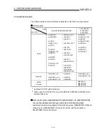
MR-H-B (MR-H-BN)
MR-J-B
MR-J2-B
MR-J2S-B *
2
7
Servo amplifier
corresponding
SSCNET
MR-J2-03B5 *
2
(Prepared by user)
8
Manual pulse
generator
–
(Prepared by user)
Recommended: MR-HDP01 (Mitsubishi Electric)
9
Connection cable
(prepared by user)
–
Cable for connecting AD75 with manual pulse generator or machine
system input signal. (Prepared by user)
Refer to manual of connected device.
10 SSCNET
cable
MR-HBUS M
MR-J2HBUS M-A
Cable for connection between the AD75 and servo amplifier
corresponding SSCNET or between the servo amplifiers corresponding
SSCNET. (Prepared by user) 0.5m, 1m, 5m
The SSCNET cable changes depending on the connected servo
amplifier. Refer to the Specifications and Installation Guide or Instruction
Manual of the used servo amplifier.
*
1
There are data that cannot be set to the servo parameters and some positioning parameters.
For the data that can be set, refer to the manual of the teaching unit.
Use a sequence program to set the data that cannot be set with the teaching unit.
*
2
Set some servo parameters using a sequence program.
(Refer to section "5.2.10 Servo parameters for MR-J2S-B" or "5.2.11 Servo parameters for MR-J2-03B5".)
Summary of Contents for A1SD75M1
Page 2: ......
Page 20: ...A 18 MEMO...
Page 22: ...MEMO...
Page 27: ...1 5 MELSEC A 1 PRODUCT OUTLINE MEMO...
Page 42: ...1 20 MELSEC A 1 PRODUCT OUTLINE MEMO...
Page 52: ...2 10 MELSEC A 2 SYSTEM CONFIGURATION MEMO...
Page 111: ...5 21 MELSEC A 5 DATA USED FOR POSITIONING CONTROL MEMO...
Page 115: ...5 25 MELSEC A 5 DATA USED FOR POSITIONING CONTROL MEMO...
Page 123: ...5 33 MELSEC A 5 DATA USED FOR POSITIONING CONTROL MEMO...
Page 127: ...5 37 MELSEC A 5 DATA USED FOR POSITIONING CONTROL MEMO...
Page 167: ...5 77 MELSEC A 5 DATA USED FOR POSITIONING CONTROL MEMO...
Page 193: ...5 103 MELSEC A 5 DATA USED FOR POSITIONING CONTROL MEMO...
Page 276: ...5 186 MELSEC A 5 DATA USED FOR POSITIONING CONTROL MEMO...
Page 332: ...7 18 MELSEC A 7 MEMORY CONFIGURATION AND DATA PROCESS MEMO...
Page 334: ...MEMO...
Page 422: ...9 64 MELSEC A 9 MAIN POSITIONING CONTROL MEMO...
Page 446: ...10 24 MELSEC A 10 ADVANCED POSITIONING CONTROL MEMO...
Page 472: ...11 26 MELSEC A 11 MANUAL CONTROL MEMO...
Page 576: ...12 104 MELSEC A 12 CONTROL AUXILIARY FUNCTIONS MEMO...
Page 745: ......


