14 - 67
MELSEC-A
14 TROUBLESHOOTING
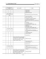
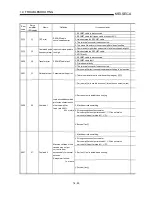
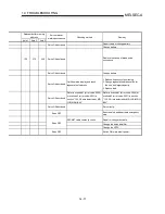
Relevant buffer memory address
Axis 1
Axis 2
Axis 3
Setting range
(Setting given in sequence program)
Remedy
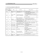
1159
1209
1259
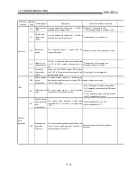
<Positioning operation speed override>
1 to 300
1176 1226 1276
<New torque value>
1 to [torque limit setting value]
24 174 324
<Torque limit setting>
1 to 500
Set a value within the setting range.
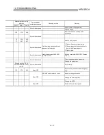
Refer to section “5.3 List of positioning
data” for the command speed.
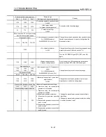
Bias speed at start
12, 13
162, 163
312, 313
<Command speed, bias speed at start>
0 to 1000000 [pulse/s]
0 to 600000000 [mm/min, etc.]
Change the command speed and bias speed at start so
that the command speed is equal to or larger than the
bias speed at start.
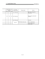
5102
<No. of read/write data>
1 to 100
Change the setting to within the setting range and issue
a read/write request. (Refer to section 7.2)
Turn the PLC READY signal [Y1D] OFF, then ON
again.
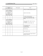
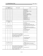
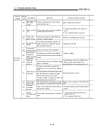
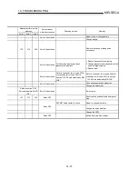
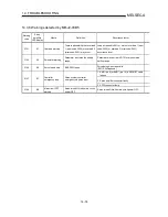
1158 1208 1258
<Speed change request>
1: Speed change request
Do not change the JOG speed during deceleration
caused by turned OFF of the JOG start signal.
New speed value
1156
1157
1206
1207
1256
1257
JOG speed limit value
48, 49
198, 199
348, 349
<New speed value or JOG speed limit
value>
0 to 1000000 [pulse/s]
0 to 600000000 [mm/min, etc.]
Change the setting to within the setting range.
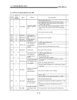
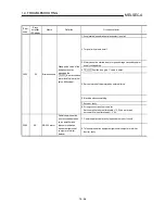
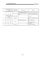
1168
1169
1218
1219
1268
1269
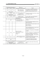
<Manual pulse generator 1 pulse input
magnification>
1 to 100
Change the manual pulse generator 1 pulse input
magnification to within the setting range.
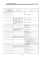
Manual pulse generator enable flag
1167 1217 1267
Manual pulse generator selection
29 179 329
<Manual pulse generator enable flag>
0: Operation using the manual pulse
generator is not enabled.
1: Operation using the manual pulse
generator is enabled.
<Manual pulse generator selection>
0: Manual pulse generator operation
ignored
1: Manual pulse generator connected to
axis 1 is used.
2: Manual pulse generator connected to
axis 2 is used.
3: Manual pulse generator connected to
axis 3 is used.
•
Change the manual pulse generator enable flag to
prohibition.
•
Change the manual pulse generator selection setting
to a value between 1 and 3.
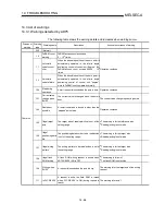
Summary of Contents for A1SD75M1
Page 2: ......
Page 20: ...A 18 MEMO...
Page 22: ...MEMO...
Page 27: ...1 5 MELSEC A 1 PRODUCT OUTLINE MEMO...
Page 42: ...1 20 MELSEC A 1 PRODUCT OUTLINE MEMO...
Page 52: ...2 10 MELSEC A 2 SYSTEM CONFIGURATION MEMO...
Page 111: ...5 21 MELSEC A 5 DATA USED FOR POSITIONING CONTROL MEMO...
Page 115: ...5 25 MELSEC A 5 DATA USED FOR POSITIONING CONTROL MEMO...
Page 123: ...5 33 MELSEC A 5 DATA USED FOR POSITIONING CONTROL MEMO...
Page 127: ...5 37 MELSEC A 5 DATA USED FOR POSITIONING CONTROL MEMO...
Page 167: ...5 77 MELSEC A 5 DATA USED FOR POSITIONING CONTROL MEMO...
Page 193: ...5 103 MELSEC A 5 DATA USED FOR POSITIONING CONTROL MEMO...
Page 276: ...5 186 MELSEC A 5 DATA USED FOR POSITIONING CONTROL MEMO...
Page 332: ...7 18 MELSEC A 7 MEMORY CONFIGURATION AND DATA PROCESS MEMO...
Page 334: ...MEMO...
Page 422: ...9 64 MELSEC A 9 MAIN POSITIONING CONTROL MEMO...
Page 446: ...10 24 MELSEC A 10 ADVANCED POSITIONING CONTROL MEMO...
Page 472: ...11 26 MELSEC A 11 MANUAL CONTROL MEMO...
Page 576: ...12 104 MELSEC A 12 CONTROL AUXILIARY FUNCTIONS MEMO...
Page 745: ......


