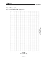
Appendix - 6
MELSEC-A
APPENDICES
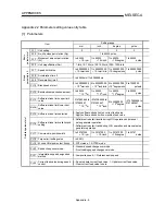
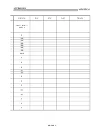
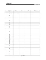
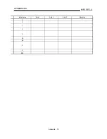
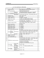
Appendix 2.2 Parameter setting value entry table
[1] Parameters
Setting range
Item
mm inch
degree
pulse
Pr.1 Unit
setting
0 1 2 3
Pr.2 No. of pulses per rotation (Ap)
1 to 65535 pulse
Pr.3
Movement amount per rotation
(Al)
1 to 65535
×
10
-1
µ
m
1 to 65535
×
10
-5
inch
1 to 65535
×
10
-5
degree
1 to 65535
pulse
B
a
sic
parameters 1
Pr.4 Unit magnification (Am)
1: 1-fold, 10: 10-fold, 100: 100-fold, 1000: 1000-fold
Pr.7 Speed limit value
1 to 600000000
×
10
-2
mm/min
1 to 600000000
×
10
-3
mm/min
1 to 600000000
×
10
-3
degree/min
1 to 600000000
pulse
Pr.8 Acceleration time 0
Pr.9 Deceleration time 0
1 to 65535ms/1 to 8388608ms
B
a
sic
parameters 2
Pr.10 Bias speed at start
0 to 600000000
×
10
-2
mm/min
0 to 600000000
×
10
-3
inch/min
0 to 600000000
×
10
-3
degree/min
0 to 1000000
pulse/s
Pr.12 Backlash compensation amount
1 to 65535
×
10
-1
µ
m
1 to 65535
×
10
-5
inch
1 to 65535
×
10
-5
degree
1 to 65535
pulse
Pr.13
Software stroke limit upper limit
value
Pr.14
Software stroke limit lower limit
value
–2147483648 to
2147483647
×
10
-1
µ
m
–2147483648 to
2147483647
×
10
-5
inch
0 to 35999999
×
10
-5
degree
–2147483648 to
2147483647
pulse
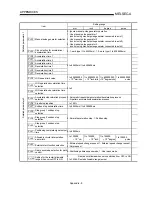
Pr.15 Software stroke limit selection
0: Apply software stroke limit on current feed value
1: Apply software stroke limit on machine feed value
Pr.16
Software stroke limit valid/invalid
setting
0: Software stroke limit invalid during JOG operation and manual
pulse generator operation
1: Software stroke limit valid during JOG operation and manual pulse
generator operation
Pr.17 Command in-position width
1 to 32767000
×
10
-1
µ
m
1 to 32767000
×
10
-5
inch
1 to 32767000
×
10
-5
degree
1 to 32767
pulse
Pr.18 Torque limit setting value
1 to 500%
Pr.19 M code ON signal output timing
0: WITH mode, 1: AFTER mode
Pr.20 Speed changeover mode
0: Standard speed changeover mode
1: Front-loading speed changeover mode
Pr.21
Interpolation speed designation
method
0: Composite speed, 1: Reference axis speed
D
e
tailed parameters 1
Pr.22
Current feed value during speed
control
0: Do not update current feed value, 1: Update current feed value
2: Clear current feed value to zero
Summary of Contents for A1SD75M1
Page 2: ......
Page 20: ...A 18 MEMO...
Page 22: ...MEMO...
Page 27: ...1 5 MELSEC A 1 PRODUCT OUTLINE MEMO...
Page 42: ...1 20 MELSEC A 1 PRODUCT OUTLINE MEMO...
Page 52: ...2 10 MELSEC A 2 SYSTEM CONFIGURATION MEMO...
Page 111: ...5 21 MELSEC A 5 DATA USED FOR POSITIONING CONTROL MEMO...
Page 115: ...5 25 MELSEC A 5 DATA USED FOR POSITIONING CONTROL MEMO...
Page 123: ...5 33 MELSEC A 5 DATA USED FOR POSITIONING CONTROL MEMO...
Page 127: ...5 37 MELSEC A 5 DATA USED FOR POSITIONING CONTROL MEMO...
Page 167: ...5 77 MELSEC A 5 DATA USED FOR POSITIONING CONTROL MEMO...
Page 193: ...5 103 MELSEC A 5 DATA USED FOR POSITIONING CONTROL MEMO...
Page 276: ...5 186 MELSEC A 5 DATA USED FOR POSITIONING CONTROL MEMO...
Page 332: ...7 18 MELSEC A 7 MEMORY CONFIGURATION AND DATA PROCESS MEMO...
Page 334: ...MEMO...
Page 422: ...9 64 MELSEC A 9 MAIN POSITIONING CONTROL MEMO...
Page 446: ...10 24 MELSEC A 10 ADVANCED POSITIONING CONTROL MEMO...
Page 472: ...11 26 MELSEC A 11 MANUAL CONTROL MEMO...
Page 576: ...12 104 MELSEC A 12 CONTROL AUXILIARY FUNCTIONS MEMO...
Page 745: ......


