4 - 16
MELSEC-A
4 INSTALLATION, WIRING AND MAINTENANCE OF THE PRODUCT
4.4 Confirming the installation and wiring
4.4.1 Items to confirm when installation and wiring are completed
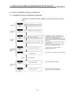
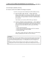
Check the (1) and (2) points when completed with the AD75 installation and wiring.
(1) Does the AD75 operate correctly? ... "Single module test"
With the "single module test", correct operation of the AD75 is confirmed by the
LED displays on the AD75. (Change the mode switch following the procedures
given in section "4.4.2 Single module test", and confirm the details displayed on
each mode LED.)
Check that there are no faults in the AD75 with the single module test.
(2) Is the servo amplifier correctly wired and set? ... "Servo starting up"
In "servo starting up", check the following four points with the servo starting up
function of the AD75 software package. (To perform "servo starting up", the servo
parameters must be set and written to the AD75 using the AD75 software
package.)
•
Checking of error/warning history
•
Checking of servo parameters and peripheral device's servo parameters
•
Checking of upper/lower limit switch operations
•
Checking of motor speed
In this manual (1) "Single module test" is explained. Refer to the AD75 Software
Package Operating Manual for details on (2) "Servo starting up".
Important
If the AD75 is faulty, or when the required signals such as the near-point dog signal and stop signal are
not recognized, unexpected accidents such as "not decelerating at the near-point dog during machine
zero point return and colliding with the stopper", or "not being able to stop with the stop signal" may
occur.
The "single module test" and "servo starting up" must be carried out not only when structuring the
positioning system, but also when the system has been changed with module replacement or rewiring,
etc.
Summary of Contents for A1SD75M1
Page 2: ......
Page 20: ...A 18 MEMO...
Page 22: ...MEMO...
Page 27: ...1 5 MELSEC A 1 PRODUCT OUTLINE MEMO...
Page 42: ...1 20 MELSEC A 1 PRODUCT OUTLINE MEMO...
Page 52: ...2 10 MELSEC A 2 SYSTEM CONFIGURATION MEMO...
Page 111: ...5 21 MELSEC A 5 DATA USED FOR POSITIONING CONTROL MEMO...
Page 115: ...5 25 MELSEC A 5 DATA USED FOR POSITIONING CONTROL MEMO...
Page 123: ...5 33 MELSEC A 5 DATA USED FOR POSITIONING CONTROL MEMO...
Page 127: ...5 37 MELSEC A 5 DATA USED FOR POSITIONING CONTROL MEMO...
Page 167: ...5 77 MELSEC A 5 DATA USED FOR POSITIONING CONTROL MEMO...
Page 193: ...5 103 MELSEC A 5 DATA USED FOR POSITIONING CONTROL MEMO...
Page 276: ...5 186 MELSEC A 5 DATA USED FOR POSITIONING CONTROL MEMO...
Page 332: ...7 18 MELSEC A 7 MEMORY CONFIGURATION AND DATA PROCESS MEMO...
Page 334: ...MEMO...
Page 422: ...9 64 MELSEC A 9 MAIN POSITIONING CONTROL MEMO...
Page 446: ...10 24 MELSEC A 10 ADVANCED POSITIONING CONTROL MEMO...
Page 472: ...11 26 MELSEC A 11 MANUAL CONTROL MEMO...
Page 576: ...12 104 MELSEC A 12 CONTROL AUXILIARY FUNCTIONS MEMO...
Page 745: ......

