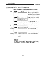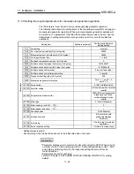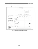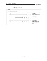
11 - 18
MELSEC-A
11 MANUAL CONTROL
Restricted items
A manual pulse generator is required to carry out manual pulse generator
operation.
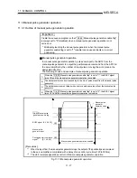
Precautions during operation
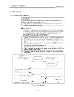
The following details must be understood before carrying out manual pulse
generator operation.
(1) The speed during manual pulse generation operation is not limited by the
" Pr.7 Speed limit value".
(2) If the " Cd.22 Manual pulse generator enable flag" is turned ON while the
AD75 is BUSY (BUSY signal ON), a warning "Start during operation" (warning
code: 100) will occur.
(3) If a stop factor occurs during manual pulse generator operation, the operation
will stop, and the BUSY signal will turn OFF.
At this time, the " Cd.22 Manual pulse generator enable flag" will be left ON,
but manual pulse generator operation will not be possible. To carry out manual
pulse generator operation again, measures must be carried out to eliminate
the stop factor. Once eliminated, the operation can be carried out again by
turning the " Cd.22 Manual pulse generator enable flag" ON OFF ON.
(4) Position/speed commands will not be output if an error occurs when the
manual pulse generator operation starts.
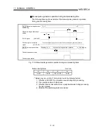
(5) The pulses input from the manual pulse generator are multiplied by 4.
REMARK
•
One AD75 module can be connected to each manual pulse generator axis.
•
The AD75 module can simultaneously output position/speed commands to the axis
1 to axis 3 servo amplifiers units by one manual pulse generator.
(1-axis to 3-axis simultaneous operation is possible.)
Errors during operation
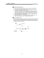
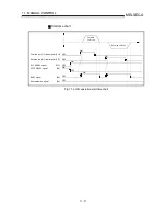
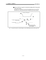
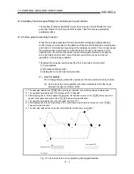
When the operation is stopped by the stroke limit (limit signal OFF), manual pulse
generator operation can be performed in the direction in which the limit signal turns
ON after an error reset. (An error will occur again if pulse input is provided in the
direction in which the limit signal turns OFF is turned ON.)
Manual pulse generator
operation possible
Manual pulse generator
operation not possible
V
Manual pulse
generator operation
Upper/lower
limit signal
ON
OFF
Summary of Contents for A1SD75M1
Page 2: ......
Page 20: ...A 18 MEMO...
Page 22: ...MEMO...
Page 27: ...1 5 MELSEC A 1 PRODUCT OUTLINE MEMO...
Page 42: ...1 20 MELSEC A 1 PRODUCT OUTLINE MEMO...
Page 52: ...2 10 MELSEC A 2 SYSTEM CONFIGURATION MEMO...
Page 111: ...5 21 MELSEC A 5 DATA USED FOR POSITIONING CONTROL MEMO...
Page 115: ...5 25 MELSEC A 5 DATA USED FOR POSITIONING CONTROL MEMO...
Page 123: ...5 33 MELSEC A 5 DATA USED FOR POSITIONING CONTROL MEMO...
Page 127: ...5 37 MELSEC A 5 DATA USED FOR POSITIONING CONTROL MEMO...
Page 167: ...5 77 MELSEC A 5 DATA USED FOR POSITIONING CONTROL MEMO...
Page 193: ...5 103 MELSEC A 5 DATA USED FOR POSITIONING CONTROL MEMO...
Page 276: ...5 186 MELSEC A 5 DATA USED FOR POSITIONING CONTROL MEMO...
Page 332: ...7 18 MELSEC A 7 MEMORY CONFIGURATION AND DATA PROCESS MEMO...
Page 334: ...MEMO...
Page 422: ...9 64 MELSEC A 9 MAIN POSITIONING CONTROL MEMO...
Page 446: ...10 24 MELSEC A 10 ADVANCED POSITIONING CONTROL MEMO...
Page 472: ...11 26 MELSEC A 11 MANUAL CONTROL MEMO...
Page 576: ...12 104 MELSEC A 12 CONTROL AUXILIARY FUNCTIONS MEMO...
Page 745: ......

