5 - 109
MELSEC-A
5 DATA USED FOR POSITIONING CONTROL
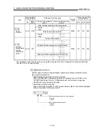
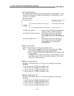
Pr.112
Load inertia ratio (Ratio of load inertia to servomotor inertia)
Set the ratio of load inertia to servomotor inertia.
When auto tuning is executed, this parameter is automatically changed to the auto
tuning result in the servo amplifier.
Pr.113
Position loop gain 1 (Model position gain)
Set the gain of the position loop.
Increase the position loop gain 1 to improve trackability in response to the position
command.
Pr.114
Speed loop gain 1 (Model speed gain)
Normally use this parameter at the initial value.
Higher setting of the speed loop gain 1 increases the response level, but is liable
to generate vibration and/or noise.
Pr.115
Position loop gain 2 (Actual position gain)
Set the gain of the position loop.
The response to load disturbance can be increased.
Higher setting of the position loop gain 2 increases the response level, but is liable
to generate vibration and/or noise.
Pr.116
Speed loop gain 2 (Actual speed gain)
Set this parameter when vibration occurs on machines of low rigidity or large
backlash.
Higher setting of the speed loop gain 2 increases the response level, but is liable
to generate vibration and/or noise.
Pr.117
Speed integral compensation
Set the time constant for integral compensation.
Pr.118
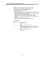
Notch filter selection
Select the frequency that matches the resonance frequency of the mechanical
system.
Pr.119
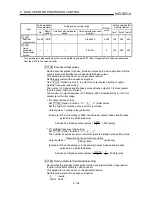
Feed forward gain
Set the feed forward gain factor for position control.
When the setting is 0%, feed forward control is not performed.
When the setting is 100%, droop pulses are not generated during constant-speed
operation.
However, if sudden acceleration/deceleration is made, overshoot increases. (The
guideline of the acceleration/deceleration time at 100% is 1s or more.)
POINT
When setting this parameter, always set "
Pr.108
Auto tuning" to "2: Invalid".
Pr.120
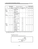
In-position range
Set the droop pulse range in which the in-position output is provided to the AD75.
Pr.121
Solenoid brake output
Set a time delay from when the solenoid brake interlock signal (MBR) turns OFF
until the servo amplifier shuts OFF the base circuit.
Summary of Contents for A1SD75M1
Page 2: ......
Page 20: ...A 18 MEMO...
Page 22: ...MEMO...
Page 27: ...1 5 MELSEC A 1 PRODUCT OUTLINE MEMO...
Page 42: ...1 20 MELSEC A 1 PRODUCT OUTLINE MEMO...
Page 52: ...2 10 MELSEC A 2 SYSTEM CONFIGURATION MEMO...
Page 111: ...5 21 MELSEC A 5 DATA USED FOR POSITIONING CONTROL MEMO...
Page 115: ...5 25 MELSEC A 5 DATA USED FOR POSITIONING CONTROL MEMO...
Page 123: ...5 33 MELSEC A 5 DATA USED FOR POSITIONING CONTROL MEMO...
Page 127: ...5 37 MELSEC A 5 DATA USED FOR POSITIONING CONTROL MEMO...
Page 167: ...5 77 MELSEC A 5 DATA USED FOR POSITIONING CONTROL MEMO...
Page 193: ...5 103 MELSEC A 5 DATA USED FOR POSITIONING CONTROL MEMO...
Page 276: ...5 186 MELSEC A 5 DATA USED FOR POSITIONING CONTROL MEMO...
Page 332: ...7 18 MELSEC A 7 MEMORY CONFIGURATION AND DATA PROCESS MEMO...
Page 334: ...MEMO...
Page 422: ...9 64 MELSEC A 9 MAIN POSITIONING CONTROL MEMO...
Page 446: ...10 24 MELSEC A 10 ADVANCED POSITIONING CONTROL MEMO...
Page 472: ...11 26 MELSEC A 11 MANUAL CONTROL MEMO...
Page 576: ...12 104 MELSEC A 12 CONTROL AUXILIARY FUNCTIONS MEMO...
Page 745: ......


