9 - 19
MELSEC-A
9 MAIN POSITIONING CONTROL
9.1.6 Interpolation control
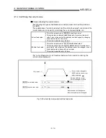
Meaning of interpolation control
In "2-axis linear interpolation control", "2-axis fixed-dimension feed control", and
"2-axis circular interpolation control", control is carried out so that linear and arc
paths are drawn using a motor set in two axis directions. This kind of control is
called "interpolation control".
In interpolation control, the axis in which the control method is set is defined as the
"reference axis", and the other axis is defined as the "interpolation axis".
The AD75 controls the "reference axis" following the positioning data set in the
"reference axis", and controls the "interpolation axis" corresponding to the
reference axis control so that a linear or arc path is drawn.
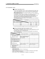
The following table shows the reference axis and interpolation axis combinations.
(In case of a 3-axis module)
Axis definition
Axis set to interpolation
control in "
Da.2 Control method"
Reference axis
Interpolation axis
Axis 1
Axis 1
Axis 2
Axis 2
Axis 2
Axis 3
Axis 3
Axis 3
Axis 1
*: In case of a 2-axis module, the reference axis is axis 1 and the interpolation axis is axis 2.
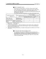
Setting the positioning data during interpolation control
When carrying out interpolation control, the same positioning data Nos. are set for
the "reference axis" and the "interpolation axis".
The following table shows the "positioning data" setting items for the reference
axis and interpolation axis.
Axis
Setting item
Reference axis setting item
Interpolation axis setting item
Da.1 Operation pattern
–
Da.2 Control method
Linear 2, Fixed-dimension feed 2,
Circular interpolation, Circular
right, Circular left
–
Da.3 Acceleration time No.
–
Da.4 Deceleration time No.
–
Da.5
Positioning address/
movement amount
Da.6 Arc address
(Only during circular interpolation,
right arc, and left arc)
(Only during circular interpolation,
right arc, and left arc)
Da.7
Command speed
–
Da.8 Dwell time
–
Same positioning data N
o
s
Da.9 M code
–
: Setting always required
: Set according to requirements (Set to "–" when not used.)
: Setting restrictions exist
– : Setting not required (Unrelated setting item, so any setting value will be ignored. Use the initial
value or a value within the setting range.)
*
: Refer to section "5.3 List of positioning data" for information on the setting details.
Summary of Contents for A1SD75M1
Page 2: ......
Page 20: ...A 18 MEMO...
Page 22: ...MEMO...
Page 27: ...1 5 MELSEC A 1 PRODUCT OUTLINE MEMO...
Page 42: ...1 20 MELSEC A 1 PRODUCT OUTLINE MEMO...
Page 52: ...2 10 MELSEC A 2 SYSTEM CONFIGURATION MEMO...
Page 111: ...5 21 MELSEC A 5 DATA USED FOR POSITIONING CONTROL MEMO...
Page 115: ...5 25 MELSEC A 5 DATA USED FOR POSITIONING CONTROL MEMO...
Page 123: ...5 33 MELSEC A 5 DATA USED FOR POSITIONING CONTROL MEMO...
Page 127: ...5 37 MELSEC A 5 DATA USED FOR POSITIONING CONTROL MEMO...
Page 167: ...5 77 MELSEC A 5 DATA USED FOR POSITIONING CONTROL MEMO...
Page 193: ...5 103 MELSEC A 5 DATA USED FOR POSITIONING CONTROL MEMO...
Page 276: ...5 186 MELSEC A 5 DATA USED FOR POSITIONING CONTROL MEMO...
Page 332: ...7 18 MELSEC A 7 MEMORY CONFIGURATION AND DATA PROCESS MEMO...
Page 334: ...MEMO...
Page 422: ...9 64 MELSEC A 9 MAIN POSITIONING CONTROL MEMO...
Page 446: ...10 24 MELSEC A 10 ADVANCED POSITIONING CONTROL MEMO...
Page 472: ...11 26 MELSEC A 11 MANUAL CONTROL MEMO...
Page 576: ...12 104 MELSEC A 12 CONTROL AUXILIARY FUNCTIONS MEMO...
Page 745: ......

