14 - 11
MELSEC-A
14 TROUBLESHOOTING
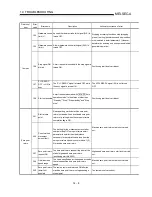
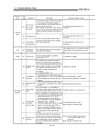
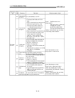
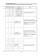
Relevant buffer memory address
Axis 1
Axis 2
Axis 3
Setting range
(Setting given in sequence program)
Remedy
70 220 370
<Zero point return method>
Near-point dog method 2), count
method 3), Data setting method
•
Use the near-point dog method 2) or count method 3) as
the zero point return method. (Refer to section 8.2.)
•
When performing data setting method machine zero
point return control, rotate the servomotor more than one
turn and then perform data setting method machine zero
point return control again.
Reset the axis error (refer to [3] in section 14.1) and start a
machine zero point return again.
101 251 401
<Amplifier setting>
0, 1
Check whether "Absolute position detection valid" is set to
the servo basic parameter "Amplifier setting" for start of
communication with the servo amplifier. (Refer to (11) in
section 7.2.)
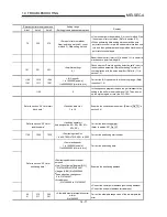
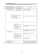
1160
1161
1210
1211
1260
1261
<JOG speed>
1 to 1000000 [pulse/s]
1 to 600000000 [mm/min, etc.]
Correct the JOG speed to within the setting range. (Refer
to section 11.2)
1146
0
In the sequence program, remove the part relevant to the
setting in the buffer memory address 1146. Then, power
up the system again or reset the PLC CPU.
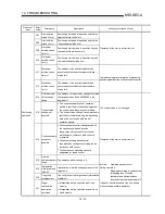
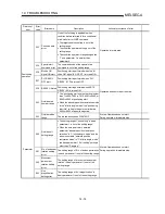
Refer to section “5.4 List of start
block data.”
<Condition data No.>
1 to 10
Examine the condition data number. (Refer to Da. 13 in
section 5.4)
Refer to section “5.5 List of
condition data.”
<Condition operator>
Axis designation: 09
H
, 0A
H
, 0B
H
, 0C
H
,
0D
H
, 0E
H
Correct the condition operator.
(Refer to section 5.5 Da. 15 )
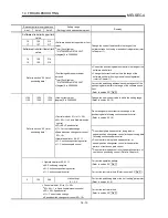
1150 1200 1250
<Positioning start No.>
1 to 600, 7000 to 7010, 9001 to 9003
Correct the positioning start number.
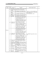
<Command speed>
1 to 1000000 [pulse/s]
1 to 600000000 [mm/min, etc.]
Correct the positioning data.
Examine the positioning address.
Refer to section “5.3 List of
positioning data.”
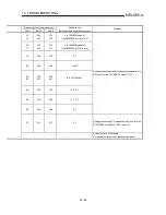
<Positioning address/movement
amount>
•
[mm] [inch] [pulse] [degree (INC)]
-2147483648 to 2147483647
•
[degree (ABS)] 0 to 35999999
•
Speed/position changeover
0 to 2147483647
<Arc address>
-2147483648 to 2147483647
•
Correct the center point address (positioning address).
•
Correct the end point address (arc address).
60
61
210
211
360
361
<Allowable circular interpolation error
width>
0 to 1000000
Correct the allowable range value of the arc interpolation
error.
Summary of Contents for A1SD75M1
Page 2: ......
Page 20: ...A 18 MEMO...
Page 22: ...MEMO...
Page 27: ...1 5 MELSEC A 1 PRODUCT OUTLINE MEMO...
Page 42: ...1 20 MELSEC A 1 PRODUCT OUTLINE MEMO...
Page 52: ...2 10 MELSEC A 2 SYSTEM CONFIGURATION MEMO...
Page 111: ...5 21 MELSEC A 5 DATA USED FOR POSITIONING CONTROL MEMO...
Page 115: ...5 25 MELSEC A 5 DATA USED FOR POSITIONING CONTROL MEMO...
Page 123: ...5 33 MELSEC A 5 DATA USED FOR POSITIONING CONTROL MEMO...
Page 127: ...5 37 MELSEC A 5 DATA USED FOR POSITIONING CONTROL MEMO...
Page 167: ...5 77 MELSEC A 5 DATA USED FOR POSITIONING CONTROL MEMO...
Page 193: ...5 103 MELSEC A 5 DATA USED FOR POSITIONING CONTROL MEMO...
Page 276: ...5 186 MELSEC A 5 DATA USED FOR POSITIONING CONTROL MEMO...
Page 332: ...7 18 MELSEC A 7 MEMORY CONFIGURATION AND DATA PROCESS MEMO...
Page 334: ...MEMO...
Page 422: ...9 64 MELSEC A 9 MAIN POSITIONING CONTROL MEMO...
Page 446: ...10 24 MELSEC A 10 ADVANCED POSITIONING CONTROL MEMO...
Page 472: ...11 26 MELSEC A 11 MANUAL CONTROL MEMO...
Page 576: ...12 104 MELSEC A 12 CONTROL AUXILIARY FUNCTIONS MEMO...
Page 745: ......

