4 - 7
MELSEC-A
4 INSTALLATION, WIRING AND MAINTENANCE OF THE PRODUCT
4.2 Installation
4.2.1 Precautions for installation
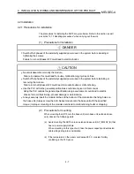
The precautions for installing the AD75 are given below. Refer to this section as well
as section "4.1.3 Handling precautions" when carrying out the work.
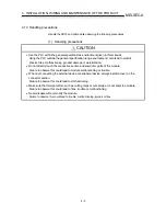
(1) Precautions for installation
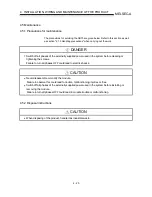
!
DANGER
Switch off all phases of the externally supplied power used in the system before cleaning or
tightening the screws.
Failure to turn all phases OFF could lead to electric shocks.
!
CAUTION
Never disassemble or modify the module.
Failure to observe this could lead to trouble, malfunctioning, injuries or fires.
Switch off all phases of the externally supplied power used in the system before installing or
removing the module.
Failure to turn all phases OFF could lead to module trouble or malfunctioning.
Use the PLC within the general specifications environment given in this manual.
Using the PLC outside the general specification range environment could lead to electric
shocks, fires, malfunctioning, product damage or deterioration.
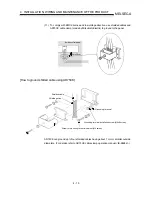
Always securely insert the module latches at the bottom of the module into the fixing holes on
the base unit. (Always screw the AnS Series module onto the base unit with the specified
torque.) Improper mounting of the module could lead to malfunctioning, faults or dropping.
(2) Precautions for mounting
When mounting the AD75 onto the base unit (main base unit, extension base
unit), observe the following points.
(a) Avoid mounting the AD75 onto an extension base unit (A5 B/A1S5 B) that
has no power supply module.
When mounting on this type of unit, take the power capacity and extension
cable voltage drop into consideration.
(b) If the temperature in the panel could exceed 55°C, consider forcibly
ventilating in the PLC panel.
Summary of Contents for A1SD75M1
Page 2: ......
Page 20: ...A 18 MEMO...
Page 22: ...MEMO...
Page 27: ...1 5 MELSEC A 1 PRODUCT OUTLINE MEMO...
Page 42: ...1 20 MELSEC A 1 PRODUCT OUTLINE MEMO...
Page 52: ...2 10 MELSEC A 2 SYSTEM CONFIGURATION MEMO...
Page 111: ...5 21 MELSEC A 5 DATA USED FOR POSITIONING CONTROL MEMO...
Page 115: ...5 25 MELSEC A 5 DATA USED FOR POSITIONING CONTROL MEMO...
Page 123: ...5 33 MELSEC A 5 DATA USED FOR POSITIONING CONTROL MEMO...
Page 127: ...5 37 MELSEC A 5 DATA USED FOR POSITIONING CONTROL MEMO...
Page 167: ...5 77 MELSEC A 5 DATA USED FOR POSITIONING CONTROL MEMO...
Page 193: ...5 103 MELSEC A 5 DATA USED FOR POSITIONING CONTROL MEMO...
Page 276: ...5 186 MELSEC A 5 DATA USED FOR POSITIONING CONTROL MEMO...
Page 332: ...7 18 MELSEC A 7 MEMORY CONFIGURATION AND DATA PROCESS MEMO...
Page 334: ...MEMO...
Page 422: ...9 64 MELSEC A 9 MAIN POSITIONING CONTROL MEMO...
Page 446: ...10 24 MELSEC A 10 ADVANCED POSITIONING CONTROL MEMO...
Page 472: ...11 26 MELSEC A 11 MANUAL CONTROL MEMO...
Page 576: ...12 104 MELSEC A 12 CONTROL AUXILIARY FUNCTIONS MEMO...
Page 745: ......

