2 - 2
MELSEC-A
2 SYSTEM CONFIGURATION
2.1 General image of system
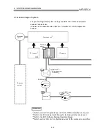
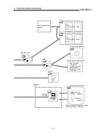
The general image of the system, including the AD75, PLC CPU and peripheral
devices is shown below.
(The Nos. in the illustration refer to the "No." in section "2.2 List of configuration
devices".
1
6
5
6
Extension
system
Converter
RS-232 cable
RS-422 cable
Conversion cable
Extension
cable
Positioning
module
I/O module
Main base unit
*
2
CPU module
*
1
*
3
* Only when using
A1SD75M
REMARK
*
1
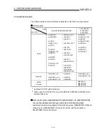
Refer to section "2.3 Applicable system" for the CPU modules that can be used.
*
2
Refer to the CPU module User's Manual for the base units that can be used.
*
3
Refer to the AD75 Software Package Operating Manual.
*
4
Refer to section "2.2 List of configuration devices" for the usable servo amplifiers.
Summary of Contents for A1SD75M1
Page 2: ......
Page 20: ...A 18 MEMO...
Page 22: ...MEMO...
Page 27: ...1 5 MELSEC A 1 PRODUCT OUTLINE MEMO...
Page 42: ...1 20 MELSEC A 1 PRODUCT OUTLINE MEMO...
Page 52: ...2 10 MELSEC A 2 SYSTEM CONFIGURATION MEMO...
Page 111: ...5 21 MELSEC A 5 DATA USED FOR POSITIONING CONTROL MEMO...
Page 115: ...5 25 MELSEC A 5 DATA USED FOR POSITIONING CONTROL MEMO...
Page 123: ...5 33 MELSEC A 5 DATA USED FOR POSITIONING CONTROL MEMO...
Page 127: ...5 37 MELSEC A 5 DATA USED FOR POSITIONING CONTROL MEMO...
Page 167: ...5 77 MELSEC A 5 DATA USED FOR POSITIONING CONTROL MEMO...
Page 193: ...5 103 MELSEC A 5 DATA USED FOR POSITIONING CONTROL MEMO...
Page 276: ...5 186 MELSEC A 5 DATA USED FOR POSITIONING CONTROL MEMO...
Page 332: ...7 18 MELSEC A 7 MEMORY CONFIGURATION AND DATA PROCESS MEMO...
Page 334: ...MEMO...
Page 422: ...9 64 MELSEC A 9 MAIN POSITIONING CONTROL MEMO...
Page 446: ...10 24 MELSEC A 10 ADVANCED POSITIONING CONTROL MEMO...
Page 472: ...11 26 MELSEC A 11 MANUAL CONTROL MEMO...
Page 576: ...12 104 MELSEC A 12 CONTROL AUXILIARY FUNCTIONS MEMO...
Page 745: ......


