A - 1
SAFETY INSTRUCTIONS
(Always read these instructions before using this equipment.)
Before using this product, please read this manual and the relevant manuals introduced in this manual
carefully and pay full attention to safety to handle the product correctly.
The instructions given in this manual are concerned with this product. For the safety instructions of the
programmable logic controller system, please read the CPU module User's Manual.
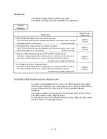
In this manual, the safety instructions are ranked as "DANGER" and "CAUTION".
!
DANGER
CAUTION
!
Indicates that incorrect handling may cause hazardous conditions,
resulting in death or severe injury.
Indicates that incorrect handling may cause hazardous conditions,
resulting in medium or slight personal injury or physical damage.
Note that the
!
CAUTION level may lead to a serious consequence according to the circumstances.
Always follow the instructions of both levels because they are important to personal safety.
Please save this manual to make it accessible when required and always forward it to the end user.
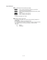
[Design Instructions]
!
DANGER
Provide a safety circuit outside the programmable logic controller so that the entire system will
operate safely even when an external power supply error or PLC fault occurs.
Failure to observe this could lead to accidents for incorrect outputs or malfunctioning.
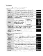
(1) Configure an emergency stop circuit and interlock circuit such as a positioning upper
limit/lower limit to prevent mechanical damage outside the PLC.
(2) The machine zero point return operation is controlled by the zero point return direction and
zero point return speed data. Deceleration starts when the near-point dog turns ON. Thus,
if the zero point return direction is incorrectly set, deceleration will not start and the
machine will continue to travel. Configure an interlock circuit to prevent mechanical
damage outside the PLC.
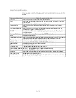
(3) When the module detects an error, normally deceleration stop or sudden stop will take
place according to the parameter stop group settings. Set the parameters to the positioning
system specifications.
Make sure that the zero point return parameter and positioning data are within the
parameter setting values.
Summary of Contents for A1SD75M1
Page 2: ......
Page 20: ...A 18 MEMO...
Page 22: ...MEMO...
Page 27: ...1 5 MELSEC A 1 PRODUCT OUTLINE MEMO...
Page 42: ...1 20 MELSEC A 1 PRODUCT OUTLINE MEMO...
Page 52: ...2 10 MELSEC A 2 SYSTEM CONFIGURATION MEMO...
Page 111: ...5 21 MELSEC A 5 DATA USED FOR POSITIONING CONTROL MEMO...
Page 115: ...5 25 MELSEC A 5 DATA USED FOR POSITIONING CONTROL MEMO...
Page 123: ...5 33 MELSEC A 5 DATA USED FOR POSITIONING CONTROL MEMO...
Page 127: ...5 37 MELSEC A 5 DATA USED FOR POSITIONING CONTROL MEMO...
Page 167: ...5 77 MELSEC A 5 DATA USED FOR POSITIONING CONTROL MEMO...
Page 193: ...5 103 MELSEC A 5 DATA USED FOR POSITIONING CONTROL MEMO...
Page 276: ...5 186 MELSEC A 5 DATA USED FOR POSITIONING CONTROL MEMO...
Page 332: ...7 18 MELSEC A 7 MEMORY CONFIGURATION AND DATA PROCESS MEMO...
Page 334: ...MEMO...
Page 422: ...9 64 MELSEC A 9 MAIN POSITIONING CONTROL MEMO...
Page 446: ...10 24 MELSEC A 10 ADVANCED POSITIONING CONTROL MEMO...
Page 472: ...11 26 MELSEC A 11 MANUAL CONTROL MEMO...
Page 576: ...12 104 MELSEC A 12 CONTROL AUXILIARY FUNCTIONS MEMO...
Page 745: ......

