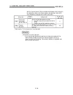
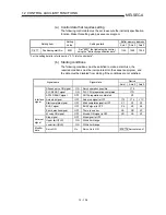
background image


12 - 87 

MELSEC-A


12   CONTROL AUXILIARY FUNCTIONS 


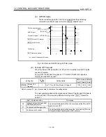
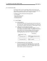
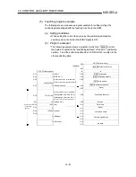
(5)   Teaching program example 

The following shows a sequence program example for setting (writing) the 

positioning data obtained with the teaching function to the AD75.  


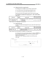
(a)   Setting conditions 

 When setting the current feed value as the positioning address/arc 

auxiliary point, write it when the BUSY signal is OFF.  


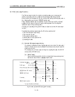
(b)   Program example 1 

 The following example shows a program in which the " Md.29  Current 

feed value" is written to the "positioning address" of the axis 1 positioning 

data No. 1, and the positioning data stored in D40 to D45 is written to the 

other positioning data.  


Positioning data

(1 positioning

amount)

(Axis 1) 

1103

D27

1

(Data No. 1)

1104

D28

1

1105

D29

(0500

H

)

1106

D30

1107

(Open) 

(Deceleration time: Use No. 0)

1108

D40

Positioning identifier

(M code No.)

1109

D41

M code 

(ms)

1110

D42

1000

Dwell time

1111

D43

0

(pulse/s)

1112

D44

100000

Command speed

1113

D45

1114

Positioning address 

1116

Arc data 

1117

PLC CPU data register

(Current feed value is the address)

1280

(0110

H

)

(Acceleration time: Use No. 1)

801

Md. 29 Current feed value

AD75 buffer memory

(Also write data other than the address)

2

272

10

(Operation pattern: Positioning complete)

(Address)

0

(Not used)

0

(Control method: axis 1 linear ABS)

1115

Cd.4  Target axis

Cd.5 Positioning data No.

Cd.6 Write pattern

(Writing request) 

(Address)

800

(Open) 

Cd.7 (Read/write request) 

to

to


Summary of Contents for A1SD75M1

Page 1: ...Mitsubishi Programmable Logic Controller A1SD75M1 M2 M3 AD75M1 M2 M3 Positioning Module User s Manual U...

Page 2: ......

Page 3: ...sible when required and always forward it to the end user Design Instructions DANGER Provide a safety circuit outside the programmable logic controller so that the entire system will operate safely ev...

Page 4: ...d to malfunctioning faults or dropping Securely connect the external device connection connector SSCNET connection connector and peripheral device connection connector into the module connector until...

Page 5: ...mit value to the slowest value and make sure that operation can be stopped immediately if a hazardous state occurs Always make sure to touch the grounded metal to discharge the electricity charged in...

Page 6: ...8 3 2 Buffer memory 873 973 1073 Section 8 4 Section 10 1 Section 12 2 2 Section 18 1 1 Appendix 2 2 Additional Section Section 1 5 Section 1 5 was altered to Section 1 6 and Section 1 6 to Section 1...

Page 7: ...ose and applications of positioning control 1 6 1 1 3 Mechanism of positioning control 1 8 1 1 4 Outline design of positioning system 1 10 1 1 5 Communicating signals between AD75 and each module 1 12...

Page 8: ...4 1 to 4 20 4 1 Outline of installation wiring and maintenance 4 2 4 1 1 Installation wiring and maintenance procedures 4 2 4 1 2 Names of each part 4 3 4 1 3 Handling precautions 4 5 4 2 Installatio...

Page 9: ...a 5 136 5 6 2 Axis monitor data 5 146 5 7 List of control data 5 168 5 7 1 System control data 5 168 5 7 2 Axis control data 5 174 6 SEQUENCE PROGRAM USED FOR POSITIONING CONTROL 6 1 to 6 38 6 1 Preca...

Page 10: ...s 9 2 9 1 1 Data required for main positioning control 9 3 9 1 2 Operation patterns of main positioning controls 9 4 9 1 3 Designating the positioning address 9 13 9 1 4 Confirming the current value 9...

Page 11: ...OG operation 11 4 11 2 1 Outline of JOG operation 11 4 11 2 2 JOG operation execution procedure 11 7 11 2 3 Setting the required parameters for JOG operation 11 8 11 2 4 Creating start programs for JO...

Page 12: ...Command in position function 12 92 12 7 6 Acceleration deceleration processing function 12 95 12 7 7 Indirectly specification function 12 99 13 COMMON FUNCTIONS 13 1 to 13 12 13 1 Outline of common fu...

Page 13: ...6 Appendix 2 3 Positioning data setting value entry table data No to Appendix 26 Appendix 3 Positioning data No 1 to 100 List of buffer memory addresses Appendix 27 Appendix 4 Comparisons with old ver...

Page 14: ...dule monitoring the positioning and testing etc using the above software package are explained Enclosed with each software package product IB 66714 13J915 GX Configurator AP Version 1 Operating Manual...

Page 15: ...dicating monitor data item Cd Symbol indicating control data item A serial No is inserted in the mark Indication of values in this manual The buffer memory address error code and warning code are indi...

Page 16: ...ATIONS AND FUNCTIONS Chapter 4 INSTALLATION WIRING AND MAINTENANCE OF THE PRODUCT Chapter 5 DATA USED FOR POSITIONING CONTROL SECTION 2 CONTROL DETAILS AND SETTING Chapter 8 ZERO POINT RETURN CONTROL...

Page 17: ...sitioning control is described Create an actual program using this program as a reference 6 7 MEMORY CONFIGURATION AND DATA PROCESS The AD75 memory configuration and data process are described Read th...

Page 18: ...rresponding SSCNET connection Motor Abbreviation for servomotor Position speed command Generic term for position command and speed command output from AD75 to servo amplifier A pulse train is converte...

Page 19: ...Quantity Part name A1SD75M1 AD75M1 A1SD75M2 AD75M2 A1SD75M3 AD75M3 External device connection connector 10136 3000VE Sumitomo 3M 1 2 3 Connector cover 10336 56 F0 008 Sumitomo 3M 1 2 3 AD75 1 A1SD75M...

Page 20: ...A 18 MEMO...

Page 21: ...ce program required for positioning control 5 To understand the memory configuration and data transmission process Read SECTION 2 for details on each control Chapter 1 PRODUCT OUTLINE 1 1 to 1 20 Chap...

Page 22: ...MEMO...

Page 23: ...oothly 1 1 Positioning control 1 2 1 1 1 Features of AD75 1 2 1 1 2 Purpose and applications of positioning control 1 6 1 1 3 Mechanism of positioning control 1 8 1 1 4 Outline design of positioning s...

Page 24: ...e AD75 and servo amplifier or between the servo amplifiers saving the wiring c The servo parameters can be set on the AD75 side and transferred to the servo amplifier by the SSCNET d The error definit...

Page 25: ...ach AD75 onto the base unit The number of input output points occupied by the PLC CPU is 32 points each There is no limit to the No of mounted modules as long as the total is within the PLC CPU No of...

Page 26: ...rn acceleration deceleration have been prepared as the acceleration deceleration methods The user can select from automatic trapezoidal acceleration deceleration or S pattern acceleration deceleration...

Page 27: ...1 5 MELSEC A 1 PRODUCT OUTLINE MEMO...

Page 28: ...ape changes the press head die is changed and the positioning pattern is changed Palletizer Servo amplifier PLC MELSEC A AD75 Conveyor control Conveyor Servomotor with brakes Position detector Reducti...

Page 29: ...Detector Servomotor Worm gears Index table Digital switch PLC MELSEC A AD75 Servo amplifier The index table is positioned at a high accuracy using the 1 axis servo Inner surface grinder PLC MELSEC A...

Page 30: ...sequence program Stores the created program The AD75 outputs the start signal and stop signal following the stored program AD75 errors etc are detected GPP function software package PLC CPU Inputs si...

Page 31: ...e side movement amount when one pulse is issued to the servo amplifier is called the movement amount per pulse This value is the min value for the workpiece to move and is also the electrical position...

Page 32: ...ontrol Current control Inverter Interface Position feedback Speed feedback Current feedback Read write etc PLC CPU AD75 Servo amplifier corresponding SSCNET refer to section 2 2 Servomotor Position sp...

Page 33: ...ent amount per pulse is indicated with 1 and the position speed command movement amount per pulse is the movement amount The command speed is calculated with 2 using the movable section speed and move...

Page 34: ...XF Y10 Y11 Y12 X7 X8 X9 X0 Peripheral device interface Interface with PLC CPU Y15 X4 X5 X6 X1 X2 X3 Y13 Y14 Y1C XA XB XC PLC CPU Stop signal External start signal Reverse run JOG start signal Y16 Y18...

Page 35: ...ls related to commands such as servo ON Signals indicating the states of servo ON OFF zero point pass etc Position speed command Commands that specify the position and speed calculated in the AD75 Mon...

Page 36: ...ngle module test Setting of the Parameters Positioning data Start block data Condition data Creation of sequence program for operation Refer to Note 2 3 4 5 6 7 8 Writing of setting data Writing of pr...

Page 37: ...tioning data etc created with the AD75 software package into the AD75 Chapter 7 AD75 Software Package Operating Manual 6 Using the GPP function software package write the created sequence program into...

Page 38: ...operation Positioning parameters Zero point return parameters Set the zero point return parameters Positioning data Set the positioning data Positioning start information Set the positioning start in...

Page 39: ...e Create sequence program for setting data When set with the AD75 software package this does not need to be created PLC CPU Write Write Write GPP function software package Create sequence program for...

Page 40: ...rol Advanced positioning control JOG opera tion Manual pulse generator operation Forced stop Servo alarm turns ON and Servo ON turns OFF Md 116 Servo status b1 b13 Each axis During error Immediate sto...

Page 41: ...600 is shown below 400 200 100 100 300 700 400 200 300 700 100 100 Axis 1 Stop position due to stop cause Designated end point position Start point address Restart Axis 2 Stop position after restart...

Page 42: ...1 20 MELSEC A 1 PRODUCT OUTLINE MEMO...

Page 43: ...stem 2 1 General image of system 2 2 2 2 List of configuration devices 2 4 2 3 Applicable system 2 6 2 4 Precautions for configuring system 2 7 2 4 1 Precautions for mounting base unit 2 7 2 4 2 Preca...

Page 44: ...on system Converter RS 232 cable RS 422 cable Conversion cable Extension cable Positioning module I O module Main base unit 2 CPU module 1 3 Only when using A1SD75M REMARK 1 Refer to section 2 3 Appli...

Page 45: ...Speed position changeover signal Stop signal AD75TU 4 3 Personal computer Peripheral device 2 Refer to the AD75 Software Package Operating Manual for details AD75 software package SW1IVD AD75P E SW0D5...

Page 46: ...are Package Operating Manual for details MR H B MR H BN MR J B MR J2 B MR J2S B 2 7 Servo amplifier corresponding SSCNET MR J2 03B5 2 Prepared by user 8 Manual pulse generator Prepared by user Recomme...

Page 47: ...ply voltage 1V or more Output current Max 20mA Power supply voltage 4 5 to 13 2VDC Current consumption 60mA Life time 100 revolutions at 200r min Radial load Max 19 6N Permitted axial loads Thrust loa...

Page 48: ...A2USHCPU S1 A1SCPU A1SJCPU S3 A2SCPU A2ASCPU S1 A52GCPU A1SHCPU A2SHCPU A1SJHCPU QnACPU Q2ACPU S1 Q2ASCPU S1 Q2ASHCPU S1 Q3ACPU Q4ACPU Q4ARCPU Q2ASCPU S1 Q2ASHCPU S1 QCPU A mode Q02CPU A Q02HCPU A Q0...

Page 49: ...annot be mounted into the final slot at the 7th extension stage of the A3CPU 3 The AD75M1 AD75M2 AD75M3 cannot be mounted into the main base unit of the A73CPU S3 Simultaneous start and interpolation...

Page 50: ...e the following precautions for configuring an absolute position detection system Infinite length feed control e g control in the given direction only is not allowed Restrictions on the usable ranges...

Page 51: ...se specifications and setting ranges have been changed from those of the MR J2 B by extension addition deletion cannot be set from the peripheral device For the items ranges that can be set from the p...

Page 52: ...2 10 MELSEC A 2 SYSTEM CONFIGURATION MEMO...

Page 53: ...cations 3 3 3 3 List of functions 3 4 3 3 1 AD75 control functions 3 4 3 3 2 AD75 main functions 3 6 3 3 3 AD75 auxiliary functions and common functions 3 8 3 3 4 Combination of AD75 main functions an...

Page 54: ...sive gases Working altitude 3 2 000m or less Installation place Within control panel Overvoltage category 1 II or less Degree of contamination 2 2 or less 1 Indicates to which power distribution secti...

Page 55: ...5455 pulse 53687091 2 to 53687091 1 m 5368 70912 to 5368 70911 inch 0 to 359 99999 degree 536870912 to 536870911 pulse Positioning range Speed position changeover control 0 to 214748364 7 m 0 to 21474...

Page 56: ...data No 1 No 2 No 3 can be set Refer to Chapter 9 MAIN POSITIONING CONTROL 3 Advanced positioning control This control executes the positioning data stored in the AD75 using the positioning start inf...

Page 57: ...itioning start information Block start Normal start Condition start Wait start Simultaneous start Stop Repeated start FOR loop Repeated start FOR condition Manual control Control with signals input fr...

Page 58: ...xed dimension feed control the Md 29 Current feed value is set to 0 when starting With 2 axis fixed dimension feed control the linear path will be fixed dimension fed with interpolation 9 2 4 9 2 5 Po...

Page 59: ...t block data set with the FOR condition to the start block data set in NEXT until the conditions set in the condition data are established 10 3 8 JOG operation Outputs a position speed command to the...

Page 60: ...feed value 12 3 4 Speed limit function If the command speed exceeds Pr 7 Speed limit value during control this function limits the commanded speed to within the Pr 7 Speed limit value setting range 12...

Page 61: ...the control use this function as a trigger for the auxiliary work 12 7 5 Acceleration deceleration process function This function adjusts the control acceleration deceleration 12 7 6 Other functions...

Page 62: ...s linear interpolation control 1 axis fixed dimension feed control Continuous path control cannot be set 2 axis fixed dimension feed control interpolation Continuous path control cannot be set Positio...

Page 63: ...tion Acceleration decelerat ion time change function Torque change function Step function Skip function M code output function Teaching function Command in position function Acceleration decelera tion...

Page 64: ...lete X4 Axis 1 X5 Axis 2 X6 Axis 3 BUSY X7 Axis 1 X8 Axis 2 X9 Axis 3 Positioning complete XA Axis 1 XB Axis 2 XC Axis 3 Error detection XD Axis 1 XE Axis 2 XF Axis 3 M code ON YF Use prohibited X10 Y...

Page 65: ...t in Pr 41 Positioning complete signal output time from the time that each positioning data No positioning control is completed This does not turn ON when Pr 41 Positioning complete signal output time...

Page 66: ...ration possible This signal makes all axes servos operable For servo ON OFF refer to section 12 4 5 Servo ON OFF function Y16 Y17 Y18 Y19 Y1A Y1B Axis 1 Axis 1 Axis 2 Axis 2 Axis 3 Axis 3 Forward run...

Page 67: ...or less 1 Pulse width 4ms or more 2ms or more 2ms or more Duty ratio 50 2 Phase difference Manual pulse generator A phase PULSE GENERATOR A Manual pulse generator B phase PULSE GENERATOR B A phase B p...

Page 68: ...ommon COM External device 34 Open 29 Open 28 Manual pulse generator PULSER B Manual pulse generator 27 Manual pulse generator PULSER A Manual pulse generator 26 Open 17 Open 16 External start signal S...

Page 69: ...start speed change request and skip request input signal from an external source Set which function to use the external start signal with in Pr 43 External start function selection Speed position cha...

Page 70: ...op signal STOP 15 Speed position changeover signal CHG 16 External start signal STRT 35 36 Common COM 9 PULSER A 27 Manual pulse generator A phase PULSER A 10 PULSER B 24VDC When not using upper limit...

Page 71: ...the precautions 4 1 Outline of installation wiring and maintenance 4 2 4 1 1 Installation wiring and maintenance procedures 4 2 4 1 2 Names of each part 4 3 4 1 3 Handling precautions 4 5 4 2 Installa...

Page 72: ...le the connector The cables used to connect the AD75 with the machine system input each input signal and the AD75 with the manual pulse generator are manufactured by soldering each signal wire onto th...

Page 73: ...X1 AX2 AX3 AX3 AX2 RS 422 AX1 MODE AX1 AX2 AX3 MODE RS 422 AX1 AX2 AX3 1SD75M3 A For AD75M3 For A1SD75M3 D75M3 A 1 17 segment LED 3 Mode switch 4 Module version label 2 Axis display LED External devic...

Page 74: ...rmation n Refer to section 13 4 LED display function for details on the displayed information 4 Module version label This label indicates the module s software version and hardware version Example Ind...

Page 75: ...deterioration Do not directly touch the conductive section and electronic parts of the module Failure to observe this could lead to module malfunctioning or trouble When not connecting the external de...

Page 76: ...on the cable Do not damage the cable sheath c Installation environment Do not install the module in the following type of environment Where the ambient temperature exceeds the 0 to 55 C range Where t...

Page 77: ...odule trouble or malfunctioning Use the PLC within the general specifications environment given in this manual Using the PLC outside the general specification range environment could lead to electric...

Page 78: ...inputs or outputs 6 Do not pull the cable when removing the cable from the AD75 or servo amplifier Hold and pull the connector connected to the AD75 or servo amplifier If the cable connected to the AD...

Page 79: ...e processing example Ground a 2mm2 or a thicker grounding wire in the shortest path Ground to the panel of the AD75 securely Strip the sheath of the shielded cable Remove the shielding wires from the...

Page 80: ...d to the panel AD75 20 to 30cm AD75CK Inside control panel How to ground shilded cable using AD75CK Shielded cable Shielding wires Screw for mounting to control cabinet M4 screw Grounding terminal Gro...

Page 81: ...e EMC directive is not required the influence of external noise may be reduced by making the configuration compliant with the EMC directive For the configuration compliant with the EMC directive refer...

Page 82: ...Connecting the connector and wire Assembling the connector section Disassemble the connector section and remove the connector Assemble the connector section Solder the wire onto the connector pin 1 D...

Page 83: ...le fixture screw B pass the cable through and then tighten screw B Screw B may be removed once and then tightened after sandwiching the cable Take care not to lose the screw and nut B Pass the cable t...

Page 84: ...4 14 MELSEC A 4 INSTALLATION WIRING AND MAINTENANCE OF THE PRODUCT c After connection the state will be as shown below...

Page 85: ...when the cable is pulled on If the cable is not sufficiently tightened with the cable fixture wind insulation tape around the cable so that it can be sufficiently tightened and pressed down b Sandwic...

Page 86: ...n of the AD75 software package To perform servo starting up the servo parameters must be set and written to the AD75 using the AD75 software package Checking of error warning history Checking of servo...

Page 87: ...station 2 Turn ON for the PLC CPU when the AD75 is mounted on the remote station the mounted station and master station and the power for the servo amplifier and servomotor connected to the AD75 3 The...

Page 88: ...tion control for speed position changeover control V P Waiting BUSY The execution is waiting due to the condition designation etc Error occurrence E The error code appears in Refer to Chapter 14 for d...

Page 89: ...changeover signal DOG Near point dog signal Changes sequentially with each press of the mode switch Step 7 Shifting to operation monitor 1 and ending the operation monitor 1 When the mode switch is pr...

Page 90: ...d in the system before cleaning or tightening the screws Failure to turn all phases OFF could lead to electric shocks CAUTION Never disassemble or modify the module Failure to observe this could lead...

Page 91: ...rvo parameters 5 7 5 1 5 Setting items for positioning data 5 9 5 1 6 Setting items for start block data 5 11 5 1 7 Setting items for condition data 5 12 5 1 8 Types and roles of monitor data 5 13 5 1...

Page 92: ...4 to Pr 45 Pr 59 to Da 1 Da 9 to Da 10 Da 18 to Da 14 Da 18 to Da 10 Da 13 The data is set with the sequence program or peripheral device In this chapter the method using the peripheral device will be...

Page 93: ...tioning system System control data Sets the clock data in the module and reads writes the positioning data Axis control data Makes settings related to the operation and controls the speed change durin...

Page 94: ...Ap Pr 3 Movement amount per rotation Al Basic para meters 1 Pr 4 Unit magnification Am 12 3 2 Pr 7 Speed limit value 12 4 1 Pr 8 Acceleration time 0 Pr 9 Deceleration time 0 12 7 6 Basic para meters...

Page 95: ...8 Stop group 1 sudden stop selection Pr 39 Stop group 2 sudden stop selection Pr 40 Stop group 3 sudden stop selection Pr 41 Positioning complete signal output time Pr 42 Allowable circular interpolat...

Page 96: ...after near point dog ON Pr 53 Zero point return acceleration time selection Pr 54 Zero point return deceleration time selection Pr 55 Zero point shift amount S S S S S Pr 56 Zero point return torque...

Page 97: ...details of the servo parameters refer to the Instruction Manual of the used servo amplifier Servo amplifier model Servo parameter MR H B MR H BN MR J B MR J2 B MR J2S B MR J2 03B5 Pr 100 Servo series...

Page 98: ...132 Option function 5 Pr 133 Option function 6 Pr 134 PI PID switching position droop Pr 136 Speed differential compensation Pr 138 Encoder output pulses Servo extension parameter Pr 149 Servo parame...

Page 99: ...ent positioning control Continuous positioning control Da 1 Operation pattern Continuous path control Da 2 Control method Linear 1 Linear 2 Fixed dimension feed 1 Fixed dimension feed 2 Circular inter...

Page 100: ...C A 5 DATA USED FOR POSITIONING CONTROL Checking the positioning data Da 1 to Da 9 are checked with the following timing 1 Startup of a positioning operation 2 When the test mode using the AD75 softwa...

Page 101: ...ch setting item Advanced positioning control Start block data setting items Block start Normal start Condition start Wait start Simulta neous start Stop Repeated start FOR loop Repeated start FOR cond...

Page 102: ...control Advanced positioning control Control Condition data Other than JUMP com mand JUMP com mand Block start Normal start Condition start Wait start Simul taneous start Stop Repeat ed start FOR loop...

Page 103: ...System monitor data Md 1 to Md 28 Monitoring the axis operation state Monitors the data related to the operating axis such as the current position and speed Axis monitor data Md 29 to Md 56 The axis...

Page 104: ...which the error occurred Md 19 Axis in which the error occurred Axis error No Md 20 Axis error No Hour minute Md 21 Axis error occurrence time Hour minute Axis error occurrence Second 100ms Md 22 Axis...

Page 105: ...ning data No being executed Monitor the remaining No of repetitions Md 53 Repeat counter Monitor the block positioning No Md 55 Block No being executed Monitor the zero point absolute position Md 43 Z...

Page 106: ...loop gain 2 used by the servo amplifier Md 110 Speed loop gain 2 Monitor Pr 117 Speed integral compensation used by the servo amplifier Md 111 Speed integral compensation Monitor the software number...

Page 107: ...em data Setting the AD75 clock data Control details Corresponding item Set the item hour Cd 1 Clock data setting hour Set the item minute second Cd 2 Clock data setting minute second Write the data se...

Page 108: ...er memory Set the write designation positioning data No in the OS memory into the buffer memory The positioning data in the OS memory designated in and is stored in the buffer memory Read completed Wr...

Page 109: ...on after each operation Cd 26 Step valid flag Set unit to carry out step Cd 27 Step mode Issue instruction to continuous operation or restart from stopped step Cd 28 Step start information Controlling...

Page 110: ...d position changeover control Cd 21 Speed position changeover control movement amount change register Set manual pulse generator operation validity Cd 22 Manual pulse generator enable flag Set scale p...

Page 111: ...5 21 MELSEC A 5 DATA USED FOR POSITIONING CONTROL MEMO...

Page 112: ...nit setting Here the value within the Table 1 range is set Table 1 on right page 20000 2 152 302 1 1 fold 1 10 10 fold 10 100 100 fold 100 Movement amount per pulse Pr 4 Unit magnification Am 1000 100...

Page 113: ...nt per pulse is less than 1 command speed variations will occur Smaller setting will increase variations and may cause machine vibration Make setting so that the movement amount per pulse is 1 or grea...

Page 114: ...vement amount per rotation Al Unit magnification Am Note The unit magnification Am is a value of 1 10 100 or 1000 If the PB 1 n value exceeds 6553 5 m adjust with the unit magnification so that the mo...

Page 115: ...5 25 MELSEC A 5 DATA USED FOR POSITIONING CONTROL MEMO...

Page 116: ...nding on the Pr 1 Unit setting Here the value within the Table 1 range is set Table 1 on right page 0 12 13 162 163 312 313 Pr 7 Speed limit value Set the maximum speed for zero point return control a...

Page 117: ...lue set with sequence program unit 0 mm 0 01 to 6000000 00 mm min 1 to 600000000 10 2 mm min 1 inch 0 001 to 600000 000 inch min 1 to 600000000 10 3 inch min 2 degree 0 001 to 600000 000 degree min 1...

Page 118: ...e is set Table 2 on right page 2147483648 18 19 168 169 318 319 0 Apply software stroke limit on current feed value 0 Pr 15 Software stroke limit selection 1 Apply software stroke limit on machine fee...

Page 119: ...65535 pulse 0 to 65535 pulse 1 to 32767 Set as a decimal 32768 to 65535 Convert into hexadecimal and set Table 2 Pr 1 setting value Value set with peripheral device unit Value set with sequence progra...

Page 120: ...et value Pr 16 Software stroke limit valid invalid setting Set whether to validate the software stroke limit during JOG operation and manual pulse generator operation Setting value setting range Setti...

Page 121: ...101 Torque output setting value or Cd 30 New torque value is used the servo amplifier limits the torque according to Cd 101 Torque output setting value or Cd 30 New torque value However when the valu...

Page 122: ...mode The M code is output simultaneously with the end of positioning and the M code ON signal turns ON Positioning complete signal X7 X8 X9 m1 m2 indicate the set M codes 01 continuous 00 end BUSY sig...

Page 123: ...5 33 MELSEC A 5 DATA USED FOR POSITIONING CONTROL MEMO...

Page 124: ...manual pulse generator 1 1 2 Use manual pulse generator 2 2 Pr 23 Manual pulse generator selection 3 Use manual pulse generator 3 3 Axis 1 1 Axis 2 2 Axis 3 3 29 179 329 0 1 word type 1 to 65535ms 0 P...

Page 125: ...s designated Designate speed for reference axis When reference axis speed is designated X axis Y axis Calculated by AD75 Note For a positioning operation that involves the circular interpolation speci...

Page 126: ...2 1 Axis 3 329 3 1 Pr 25 Size selection for acceleration deceleration time Select the setting size for the acceleration deceleration time The setting size such as Acceleration time 0 to 3 Deceleratio...

Page 127: ...5 37 MELSEC A 5 DATA USED FOR POSITIONING CONTROL MEMO...

Page 128: ...iffers depending on the Pr 1 Unit setting Here the value within the Table 2 range is set Table 2 on right page 20000 48 49 198 199 348 349 0 Pr 8 Acceleration time 0 0 1 Pr 26 Acceleration time 1 1 2...

Page 129: ...eed limit value Set the maximum speed for JOG operation Note Set the JOG speed limit value to less than Pr 7 Speed limit value If the speed limit value is exceeded the JOG speed limit value error erro...

Page 130: ...setting Here the value within the Table 1 range is set Table 1 on right page 1000 54 55 204 205 354 355 Pr 38 Stop group 1 sudden stop selection 0 Normal deceleration stop 0 56 206 356 Pr 39 Stop gro...

Page 131: ...e using the Sin curve as shown below A B B 2 B 2 V t V t b a 0 7 b a sin curve S pattern ratio B A 100 Example Positioning speed Positioning speed When S pattern ratio is 100 When S pattern ratio is 7...

Page 132: ...e When a sudden stop cause occurs the deceleration starts following the sudden stop deceleration time 3 Positioning stop When a sudden stop cause does not occur the decelera tion starts toward the sto...

Page 133: ...op signal from peripheral device PLC READY signal OFF Stop group 3 External stop signal Stop signal from PLC Error occurrence excluding errors in stop group 1 and 2 Stop caused by an ON OFF change at...

Page 134: ...rnal start function selection 2 Skip request 2 0 62 212 362 0 Positioning address pass mode 0 Pr 44 Near pass mode selection for path control 1 Near pass mode 1 0 66 216 366 Pr 150 Setting for the res...

Page 135: ...erpolation will be carried out to the set end point address while compensating the error with spiral interpolation The allowable circular interpolation error width is set in the reference axis buffer...

Page 136: ...oning data is passed but the speed output when the corresponding positioning address is passed may drop momentarily 1 Near pass mode Since positioning is not performed at the address designated in the...

Page 137: ...zero point return An error occurs when the zero point is not detected 4 Count method 1 After decelerating at the near point dog ON move the designated distance stop at the zero point and then complet...

Page 138: ...vement amount after near point dog ON is reached after the near point dog turned ON 4 Move to the first zero point single pulse output per motor revolution and complete the machine zero point return N...

Page 139: ...r point dog method is performed t Pr 48 Zero point return speed Pr 49 Creep speed V Zero point Near point dog ON OFF 1 2 3 4 8 Count method 3 1 Start machine zero point return Start movement at the Pr...

Page 140: ...4 75 224 225 374 375 Pr 46 Zero point return direction Set the direction to start movement when starting machine zero point return 0 Positive direction address increment direction Moves in the directi...

Page 141: ...inch 0 001 to 600000 000 inch min 1 to 600000000 10 3 inch min 2 degree 0 001 to 600000 000 degree min 1 to 600000000 10 3 degree min 3 pulse 1 to 1000000 pulse s 1 to 1000000 pulse s Pr 47 Zero poin...

Page 142: ...le 1 on right page 1 76 77 226 227 376 377 0 Do not retry zero point return with limit switch 0 Pr 50 Zero point return retry 1 Retry zero point return with limit switch 1 0 78 228 378 Pr 49 Creep spe...

Page 143: ...nd then will move in the direction opposite the designated zero point return direction 3 If it is detected that the near point dog signal has turned OFF from turning ON while moving in the opposite di...

Page 144: ...Acceleration time 2 2 Pr 53 Zero point return acceleration time selection 3 Pr 28 Acceleration time 3 3 0 82 232 382 0 Pr 9 Deceleration time 0 0 1 Pr 29 Deceleration time 1 1 2 Pr 30 Deceleration tim...

Page 145: ...as shown below Machine zero point return operation Speed limit value Pr 7 Zero point return speed Pr 48 Deceleration distance Creep speed Pr 49 Actual decel eration time Deceleration time Set 175 or...

Page 146: ...and set 0 89 239 389 0 Standard mode 0 Pr 59 Absolute position restoration selection 1 Infinite length mode 1 0 91 241 391 When Pr 59 is set with the peripheral device setting can be made using GX Co...

Page 147: ...peed as the setting value 1 Designate Pr 49 Creep speed as the setting value Pr 58 Dwell time during zero point return retry When zero point return retry is validated when 1 is set for Pr 50 set the s...

Page 148: ...BU 01H 02 MR RB013 02H 03 MR RB033 03H 05 MR RB32 05H 06 MR RB34 06H 07 MR RB54 07H 08 MR RB30 08H 09 MR RB50 09H 0B MR RB31 0BH 0C MR RB51 0CH 0E Standard fan 0EH External dynamic brake selection 0...

Page 149: ...tandard fan External dynamic brake valid invalid selection 0 External dynamic brake invalid 1 External dynamic brake valid 0 When using the converter unit MR RB 138 4 with the large capacity type serv...

Page 150: ...g No 8 ATU 2 Invalid 2 1 108 258 408 1 Normal Low response 0001H 2 Normal Low middle response 0002H 3 Normal Middle response 0003H 4 Normal Middle high response 0004H 5 Normal High response 0005H 8 La...

Page 151: ...ype Setting value Response Guideline for corresponding machine rigidity GDL2 GDM2 guideline for load inertia Guideline for position settling time GDL2 GDM2 guideline within 5 times 50 to 300ms 10 to 7...

Page 152: ...tion No 18 NCH 7 161 7 0 118 268 418 Pr 119 Feed forward gain No 19 FFC 0 to 100 0 to 100 0 119 269 419 Pr 120 In position range No 20 INP 0 to 50000 pulse 0 to 50000 pulse 100 120 270 420 Pr 121 Sole...

Page 153: ...oop gain 2 Actual speed gain Set this parameter when vibration occurs on machines of low rigidity or large backlash Higher setting of the speed loop gain 2 increases the response level but is liable t...

Page 154: ...4 wire Supports long distance cables 1 H 0000H 123 273 423 Motor less operation selection 0 Invalid 0 H 1 Valid 1 H Solenoid brake interlock output selection 0 Independent of motor speed Output under...

Page 155: ...ss operation is valid signals can be output or the status displayed without connection of the servomotor Solenoid brake interlock output selection Selection of 0 Independent of motor speed Output unde...

Page 156: ...lse 1 4 7H 7 H 8 Droop pulse 1 16 8H 8 H 9 Droop pulse 1 32 9H 9 H A Droop pulse 1 64 AH A H Pre alarm data sampling time selection 0 1 77ms 0 H 1 3 55ms 1 H 2 7 11ms 2 H 3 14 2ms 3 H Pr 129 Pre alarm...

Page 157: ...7 Droop speed 1 4 8 Droop speed 1 16 9 Droop speed 1 32 A Droop speed 1 64 0 1 77ms 1 3 55ms 2 7 11ms 3 14 2ms 4 28 4ms Set any of 0 to A Refer to the settings of the following data selection 1 Pr 13...

Page 158: ...102 Regenerative brake resister No 2 REG 1 External dynamic brake valid 1 H 0000H 102 252 402 0000H HA SH standard 0000H 0003H HA FH 0003H Pr 103 Motor type No 3 MTY 0005H HA MH 0005H 0000H 103 253 4...

Page 159: ...3 MR RB033 04 MR RB064 2 05 MR RB32 06 MR RB34 07 MR RB54 0F MR RB064 Pr 103 Motor type Set the motor type to be used Pr 104 Motor capacity Set 100 times greater than the output capacity kW of the mot...

Page 160: ...ning for ordinary operation 1 Pr 108 Auto tuning No 8 ATU 2 Invalid 2 1 108 258 408 1 Normal Low response 1 2 Normal Low middle response 2 3 Normal Middle response 3 4 Normal Middle high response 4 Pr...

Page 161: ...valid after auto tuning Pr 109 Servo response setting Set this parameter to increase the response of the servo Description Machine type Setting value Response Guideline for corresponding machine rigid...

Page 162: ...225 5 6 188 6 Pr 118 Notch filter selection No 18 NCH 7 161 7 0 118 268 418 Pr 119 Feed forward gain No 19 FFC 0 to 100 0 to 100 0 119 269 419 Pr 120 In position range No 20 INP 0 to 50000 pulse 0 to...

Page 163: ...response level but is liable to generate vibration and or noise Pr 116 Speed loop gain 2 Actual speed gain Set this parameter when vibration occurs on machines of low rigidity or large backlash Highe...

Page 164: ...0 2 25KHz Standard 0 H 3 9 0KHz Low noise 3 H Serial encoder cable selection 0 2 wire 0 H Pr 123 Option function 1 No 23 OP1 1 4 wire Supports long distance cables 1 H 0000H 123 273 423 Motor less ope...

Page 165: ...tinuous output of the servomotor reduces Serial encoder cable selection Select the serial encoder cable to be used H Carrier frequency selection 0 2 5KHz Standard 3 9 0KHz Low noise Serial encoder cab...

Page 166: ...30 ZSP 0 to 10000 r min 0 to 10000 r min 50 130 280 430 Pr 131 Error excessive alarm level No 31 ERZ 1 to 1000 kpulse 1 to 1000 kpulse 80 131 281 431 Pr 136 Speed differential compensation No 36 VDC 0...

Page 167: ...5 77 MELSEC A 5 DATA USED FOR POSITIONING CONTROL MEMO...

Page 168: ...ction 0 External dynamic brake invalid 0 H Pr 102 Regenerative brake resister No 2 REG 1 External dynamic brake valid 1 H 0000H 102 252 402 Pr 103 Motor type No 3 MTY 0080H Automatic setting 0080H 000...

Page 169: ...l dynamic brake valid Pr 103 Motor type Set the motor type to be used When the motor type is set to 0080H Automatic setting Pr 104 Motor capacity is automatically set in the servo amplifier However se...

Page 170: ...8 ATU 2 Invalid 2 1 108 258 408 1 Normal Low response 0001H 2 Normal Low middle response 0002H 3 Normal Middle response 0003H 4 Normal Middle high response 0004H 5 Normal High response 0005H 8 Large...

Page 171: ...guideline for load inertia Guideline for position settling time GDL2 GDM2 guideline within 5 times 50 to 300ms 10 to 70ms Normal Standard mode 1 2 3 4 5 Low response Middle response High response Low...

Page 172: ...tion No 18 NCH 7 161 7 0 118 268 418 Pr 119 Feed forward gain No 19 FFC 0 to 100 0 to 100 0 119 269 419 Pr 120 In position range No 20 INP 0 to 50000 pulse 0 to 50000 pulse 100 120 270 420 Pr 121 Sole...

Page 173: ...oop gain 2 Actual speed gain Set this parameter when vibration occurs on machines of low rigidity or large backlash Higher setting of the speed loop gain 2 increases the response level but is liable t...

Page 174: ...0 H Pr 123 Option function 1 No 23 OP1 1 4 wire Supports long distance cables 1 H 0000H 123 273 423 Slight vibration suppression function selection 0 Invalid 0 H 1 Valid 1 H Motor less operation sele...

Page 175: ...1 4 wire Supports long distance cables 0 0 Pr 124 Option function 2 Set the option function 2 slight vibration suppression function selection motor less operation selection Slight vibration suppressio...

Page 176: ...to 999 mV 0 128 278 428 Pr 130 Zero speed No 30 ZSP 0 to 10000 r min 0 to 10000 r min 50 130 280 430 Pr 131 Error excessive alarm level No 31 ERZ 1 to 1000 kpulse 1 to 1000 kpulse 80 131 281 431 PI PI...

Page 177: ...d at which the motor speed is judged as zero Pr 131 Error excessive alarm level Set the range in which a droop pulse excess alarm will be output Pr 132 Option function 5 Select the PI PID control swit...

Page 178: ...B 0001H 2 MR J2 B 0002H Pr 100 Servo series 3 Other 001EH 0000H 100 250 400 0 Absolute position detection invalid 0 Pr 101 Amplifier setting No 1 AMS 1 Absolute position detection valid 1 0 101 251 40...

Page 179: ...ction 00 External regenerative brake option not used 05 MR RB32 08 MR RB30 09 MR RB50 10 MR RB032 11 MR RB12 External dynamic brake valid invalid selection 0 External dynamic brake invalid 1 External...

Page 180: ...0006H 0007H 8 70Hz 0008H 9 85Hz 0009H A 105Hz 000AH B 130Hz 000BH C 160Hz 000CH 000DH 000EH Pr 109 Servo response setting No 9 RSP 000FH 0001H 109 259 409 This parameter is made valid when the servo a...

Page 181: ...ence program Pr 109 Servo response setting Set the response level of auto tuning Setting value Response Guideline for machine resonance frequency 1 15 Hz 2 20 Hz 3 25 Hz 4 30 Hz 5 35 Hz 6 45 Hz 7 55 H...

Page 182: ...er when the PLC CPU is powered ON or reset or the PLC READY signal Y1D turns ON When auto tuning is executed and operation is performed however they are changed to the optimum values in the servo ampl...

Page 183: ...The response to load disturbance can be increased Higher setting of the position loop gain 2 increases the response level but is liable to generate vibration and or noise When Pr 108 Auto tuning is s...

Page 184: ...suppression filter 1 Set the machine resonance suppression filter 1 notch frequency notch depth H Notch frequency 0 00 01 02 03 04 05 06 07 08 09 0A 0B 0C 0D 0E 0F 10 11 12 13 14 15 16 17 18 19 1A 1B...

Page 185: ...or more POINT When setting this parameter always set Pr 108 Auto tuning to 2 Manual mode 2 Pr 120 In position range Set the droop pulse range in which the in position output is provided to the AD75 S...

Page 186: ...nd 4 H 4H 5 Command speed 8V max speed 5 H 5H 6 Droop pulse 10V 128 pulses 6 H 6H 7 Droop pulse 10V 2048 pulses 7 H 7H 8 Droop pulse 10V 8192 pulses 8 H 8H 9 Droop pulse 10V 32768 pulses 9 H 9H A Droo...

Page 187: ...Current command 8V max current command 5 Command speed 8V max speed 6 Droop pulse 10V 128 pulses 7 Droop pulse 10V 2048 pulses 8 Droop pulse 10V 8192 pulses 9 Droop pulse 10V 32768 pulses A Droop puls...

Page 188: ...ibration suppression control No 25 LPF 1 H 0000H 125 275 425 This parameter is made valid when the servo amplifier is powered OFF then ON again after it has been transferred from the AD75 to the servo...

Page 189: ...trol in which the servo amplifier detects machine resonance and automatically sets the filter characteristics to suppress mechanical system vibration is made invalid or valid or is held Adaptive vibra...

Page 190: ...switching 0 PI control is always valid 0 1 Switched to PID control when value set to PI PID switching position droop is reached or exceeded during position control 1 Pr 132 Option function 5 No 32 OP5...

Page 191: ...be set on the peripheral device Set this parameter with a sequence program Serial communication baud rate selection Select the serial communication baud rate Serial communication response delay time S...

Page 192: ...ually output is 1 4 times greater than the preset number of pulses The maximum output frequency is 1 3Mpulse after multiplication by 4 Use this parameter within this range For output pulses setting Se...

Page 193: ...5 103 MELSEC A 5 DATA USED FOR POSITIONING CONTROL MEMO...

Page 194: ...0 400 Pr 101 Amplifier setting No 1 Use prohibited set the default value 0 101 251 401 Pr 102 Regenerative brake resister No 2 Use prohibited set the default value 0000H 102 252 402 Pr 103 Motor type...

Page 195: ...y of 1 to 9999 in hexadecimal The value is automatically set in the servo amplifier according to the used servomotor POINT Always set the motor capacity to other than 0 At the default value 0 operatio...

Page 196: ...ion 1 Pr 108 Auto tuning No 8 ATU 2 Invalid 2 1 108 258 408 1 Normal Low response 0001H 2 Normal Low middle response 0002H 3 Normal Middle response 0003H 4 Normal Middle highresponse 0004H 5 Normal Hi...

Page 197: ...machine rigidity GDL2 GDM2 guideline for load inertia Guideline for position settling time GDL2 GDM2 guideline within 5 times 50 to 300ms 10 to 70ms Normal Standard mode 1 2 3 4 5 Low response Middle...

Page 198: ...tion No 18 NCH 7 161 7 0 118 268 418 Pr 119 Feed forward gain No 19 FFC 0 to 100 0 to 100 0 119 269 419 Pr 120 In position range No 20 INP 0 to 50000 pulse 0 to 50000 pulse 100 120 270 420 Pr 121 Sole...

Page 199: ...oop gain 2 Actual speed gain Set this parameter when vibration occurs on machines of low rigidity or large backlash Higher setting of the speed loop gain 2 increases the response level but is liable t...

Page 200: ...his parameter is made valid when the servo amplifier is powered OFF then ON again after it has been transferred from the AD75 to the servo amplifier Pr 123 Option function 1 Set the option function 1...

Page 201: ...ys valid 0 1 Switched to PID control when value set to PI PID switching position droop is reached or exceeded during position control 1 Pr 132 Option function 5 No 32 OP5 2 PID control is always valid...

Page 202: ...2314 2315 2316 2317 2318 2319 2320 2321 2322 2324 2325 2326 2327 2328 2329 3280 3281 3282 3284 3285 3286 3287 3288 3289 3290 3291 3292 3294 3295 3296 3297 3298 3299 b15 b12 b0 b4 b8 0 0 Da 1 Da 2 Da 3...

Page 203: ...Positioning address movement amount Buffer memory address Positioning identifier 100 99 The positioning data setting items Da 1 to Da 9 are explained in the following section The buffer memory addres...

Page 204: ...ion ABS CW 09H ABS Circular left Circular interpolation control with center point designation ABS CCW 0AH INC Circular right Circular interpolation control with center point designation INC CW 0BH INC...

Page 205: ...operation does not stop at each positioning data Da 2 Control method Set the control method for carrying out positioning control Note When JUMP command is set for the control method the Da 8 Dwell tim...

Page 206: ...he absolute position detection system Refer to section 12 6 Absolute position restoration function 1 Absolute ABS system Current value charge The setting value positioning address for the ABS system a...

Page 207: ...Forward run Speed control 0DH Reverse run Speed control 0EH JUMP command 20H Setting not required Setting not required ABS Circular interpolation 07H ABS Circular right 09H ABS Circular left 0AH Set...

Page 208: ...ft 0CH Circular interpolation control is not possible When Pr 1 Unit setting is pulse Da 2 setting value Value set with peripheral device pulse Value set with sequence program 1 pulse ABS Linear 1 01H...

Page 209: ...0FH Reverse run speed position 10H Set the movement amount 0 to 21474 83647 Set the movement amount 0 to 2147483647 Forward run Speed control 0DH Reverse run Speed control 0EH JUMP command 20H Settin...

Page 210: ...lar interpolation with auxiliary point designation set the auxiliary point passing point address as the arc address 2 When carrying out circular interpolation with center point designation set the cen...

Page 211: ...osition 10H JUMP command 20H Current value change 11H Setting not required Setting not required 1 Decimal points cannot be used in the sequence program so input the setting value as an integer The val...

Page 212: ...r left 0CH Set the movement amount 2147483648 to 2147483647 Set the movement amount 2147483648 to 2147483647 ABS Linear 1 01H ABS Linear 2 04H INC Linear 1 02H INC Linear 2 05H Fixed dimension feed 1...

Page 213: ...ar left 0CH Set the movement amount 21474 83648 to 21474 83647 Set the movement amount 2147483648 to 2147483647 ABS Linear 1 01H ABS Linear 2 04H INC Linear 1 02H INC Linear 2 05H Fixed dimension feed...

Page 214: ...d limit value positioning will be carried out at the speed limit value 2 If 1 is set for the command speed the current speed speed set for previous positioning data No will be used for positioning con...

Page 215: ...00000 10 3 degree min 3 pulse 1 to 1000000 pulse s 1 to 1000000 pulse s Table 2 Da 2 setting value Setting item Value set with peripheral device Value set with sequence program JUMP command 20H Positi...

Page 216: ...pattern ON V t V t V t 1 When Da 1 Operation pattern in 00 Positioning complete Set the time from when the positioning ends to when the positioning complete signal turns ON as the dwell time Positioni...

Page 217: ...axis in the buffer memory address shown on the left One start block data item is configured of the items shown in the bold box 1st point 2nd point 50th point Setting item Buffer memory address Setting...

Page 218: ...he nth point block between 1 and 50 in the Cd 31 Positioning starting point No This number between 7000 and 7010 is called the block No With the AD75 the start block data 50 points and condition data...

Page 219: ...sitioning data No 1 to 600 01H to 258H 01H to 258H b15 b0 b3 b7 b11 0 0 0 Start data No Shape 0000H 4300 4550 4800 0 Normal start 00H 1 Condition start 01H 2 Wait start 02H 3 Simultaneous start 03H 4...

Page 220: ...top the control wait until the conditions are established 03H Simultaneous start Simultaneous execute output position speed commands at same timing the positioning data with the No designated for the...

Page 221: ...mory ddress Setting item Buffer memory address Open Up to 10 condition data items can be set stored for each axis in the buffer memory address shown on the left One condition data item is configured o...

Page 222: ...Cd 11 Positioning start No and set the start block data for the nth point block between 1 and 50 in the Cd 31 Positioning starting point No This number between 7000 and 7010 is called the block No Wit...

Page 223: ...A Axis 2 designation 0AH 0B Axis 1 and axis 2 designation 0BH 0C Axis 3 designation 0CH 0D Axis 1 and axis 3 designation 0DH Condition identifier Da 15 Condition operator 0E Axis 2 and axis 3 designat...

Page 224: ...etails 07H DEV ON 01H Device X 02H Device Y 08H DEV OFF When the input output signal ON OFF is set as the condition set ON or OFF 01H P1 03H Buffer memory 1 word 04H Buffer memory 2 word 06H P1 P2 Set...

Page 225: ...600 01H to 258H High order 16 bit Axis 2 positioning data No 1 to 600 01H to 258H Da 18 Parameter 2 Set the parameters as required for the Da 15 Condition operator Da 15 Condition operator Setting val...

Page 226: ...ur minute The software clock data created by the system in the AD75 is stored This is used to record the history occurrence time Note To utilize the clock data the correct time must be set from the PL...

Page 227: ...code Monitor value Name OS type Corresponding OS name 452 453 454 455 Monitoring is carried out with a hexadecimal Example When OS version is V00M 0 3 456 0 4 D M V 5 457 6 3 0 0 V00M Converted with...

Page 228: ...rt time Hour minute The starting time is stored Software clock data created by system in AD75 Monitoring is carried out with a hexadecimal 0 b15 b12 0 0 1 0 1 0 1 0 0 1 1 0 0 0 0 b8 b4 b0 5 3 0 1 0 to...

Page 229: ...ory Pointer No The pointer No following the pointer No where the latest start history is stored is stored Item Buffer memory address A pointer No is assigned to each block of buffer memory that config...

Page 230: ...time Hour minute The error detection time is stored Software clock data created by system in AD75 Monitoring is carried out with a hexadecimal 0 b15 b12 0 0 1 0 1 0 1 0 0 1 1 0 0 0 0 b8 b4 b0 5 3 0 1...

Page 231: ...e previous history will be cleared 15 618 619 620 621 622 14 613 614 615 616 617 13 608 609 610 611 612 12 603 604 605 606 607 11 598 599 600 601 602 10 593 594 595 596 597 9 588 589 590 591 592 8 583...

Page 232: ...Monitoring is carried out with a hexadecimal 0 b15 b12 0 0 1 0 1 0 1 0 0 1 1 0 0 0 0 b8 b4 b0 5 3 0 1 0 to 2 0 to 3 0 to 5 00 to 23 00 to 59 0 to 9 5 1 3 0 Buffer memory stored with BCD code Monitor v...

Page 233: ...Md 19 Axis in which the error occurred Md 20 Axis error No Md 21 Axis error occurrence time Hour minute Md 21 Axis error occurrence time Second 100ms The pointer No following the pointer No where the...

Page 234: ...75 Monitoring is carried out with a hexadecimal 0 b15 b12 0 0 1 0 1 0 1 0 0 1 1 0 0 0 0 b8 b4 b0 5 3 0 1 0 to 2 0 to 3 0 to 5 00 to 23 00 to 59 0 to 9 5 1 3 0 Buffer memory stored with BCD code Monito...

Page 235: ...4 Axis in which the warning occurred Md 25 Axis warning No Md 26 Axis warning occurrence time Hour minute Pointer No Warning history Md 27 Axis warning occurrence time Second 100ms The pointer No foll...

Page 236: ...es Characteristic coordinates determined with machine Update timing 56 8ms Md 31 Feedrate The output speed average value per 910ms commanded by the AD75 is stored May be different from the actual moto...

Page 237: ...cimal integer value Converted from hexadecimal to decimal 1 mm 5 inch 5 degree 0 pulse n Unit n 2 mm min 3 inch min 3 degree min 0 pulse s Unit Unit conversion table Unit conversion Actual value High...

Page 238: ...e axis warning No is cleared set to 0 Md 35 Axis operation status The axis operation state is stored Md 36 Current speed Da 7 Command speed of the positioning data currently in execution is stored Whe...

Page 239: ...ped Interpolating In JOG operation In manual pulse generator operation Analyzing Special start waiting In zero point return In position control In speed control In speed control for speed position con...

Page 240: ...date timing is 910ms Md 38 Speed position changeover control positioning amount The value set as the movement amount for the position control to end after changing to position control with the speed p...

Page 241: ...ee 0 pulse n Unit n 2 mm min 3 inch min 3 degree min 0 pulse s Unit Unit conversion table Unit conversion Actual value High order buffer memory Low order buffer memory R 10n Unit conversion table Md 3...

Page 242: ...during speed control or speed position changeover control This signal turns OFF during axis movement in each operation Zero point return request flag This signal turns ON when the power is turned ON w...

Page 243: ...ored items Meaning Not used In speed control flag Speed position changeover latch flag Command in position flag Zero point return request flag Zero point return complete flag Axis warning detection Sp...

Page 244: ...ned ON and the zero point return basic parameter Pr 47 Zero point address is stored when the machine zero point return is completed The zero point absolute position value is changed when the current v...

Page 245: ...Example 820 High order buffer memory Example 821 Sorting Decimal integer value Converted from hexadecimal to decimal 1 mm 5 inch 5 degree 0 pulse n Unit n 2 mm min 3 inch min 3 degree min 0 pulse s U...

Page 246: ...oning data No setting value The positioning data No indicated by the start data pointer currently being executed is stored Md 49 In speed limit flag If the speed exceeds the Pr 7 Speed limit value due...

Page 247: ...out with a decimal display Storage value Monitor value setting value Md 46 00 04 07 01 02 03 06 05 1 to 10 0 to 255 Stored contents Storage value None None Condition data No No of repetitions 0 828 92...

Page 248: ...s value is decremented 1 at the end of the repetition loop The loop ends when 0 is reached 0 is stored for an infinite loop Md 54 Positioning data No being executed The positioning data No currently b...

Page 249: ...34 1034 Monitoring is carried out with a decimal display Storage value 1 to 600 Monitor value 0 835 935 1035 Monitoring is carried out with a decimal display Storage value 0 7000 to 7010 Monitor value...

Page 250: ...02 Deviation counter value The droop pulse count of the deviation counter is stored The update timing is 56 8ms Md 103 Motor speed The motor speed is stored with a sign Unit 0 1r min The update timing...

Page 251: ...8 b20 b16 b24 Example 849 A B C D R Decimal integer value Actual value Md 100 Zero point return re movement amount Md 101 Real current value Unit conversion Unit conversion table n 1 5 inch 5 degree 0...

Page 252: ...stored Unit rad s When auto tuning is valid the value calculated by auto tuning is stored Md 109 Position loop gain 2 The Pr 115 Position loop gain 2 servo parameter value set to the servo amplifier...

Page 253: ...with a decimal Monitor value Storage value 0 1 0 858 958 1058 0 859 959 1059 0 860 960 1060 0 861 961 1061 Monitoring is carried out with a decimal Storage value rad s Monitor value 0 862 962 1062 Mo...

Page 254: ...status ON indicates servo ON and OFF indicates servo OFF Zero point pass Indicates whether the zero point Z phase of the pulse encoder installed on the servomotor has been passed or not after a start...

Page 255: ...eter No 31 Pr 131 b1 Servo parameter No 17 Pr 117 0000H 871 971 1071 Monitoring is carried out with a hexadecimal Monitor value b15 b0 b4 b8 b12 b0 Servo parameter No 32 Pr 132 b4 Servo parameter No 3...

Page 256: ...bsolute position restoration mode is not switched the value is incremented by 2 The update timing is 56 8ms Md 121 Absolute position restoration mode The mode for absolute position restoration is stor...

Page 257: ...nitor value 0 878 978 1078 Monitoring is carried out with a hexadecimal Address Reference Buffer memory status at the access count of 9 000 000 000 times 9 000 000 000 0000 0002 1871 1A00 16 b15 b0 88...

Page 258: ...he clock data minute second from the PLC CPU is set after the AD75 power is turned ON Cd 3 Clock data writing After setting the clock data in Cd 1 and Cd 2 when setting the data in Md 5 and Md 6 as th...

Page 259: ...econd 00 to 59 minute 0 to 5 0 to 9 0 to 5 0 to 9 0 Setting value Buffer memory 0000 1101 Set with a hexadecimal 0 0 0 1 0 0 0 0 0 0 0 0 0 0 0 0 0 0 1 b15 b0 b4 b8 b12 0 Setting value Buffer memory Cl...

Page 260: ...ddress field Set how to write data into the positioning address and arc address of the positioning data Positioning data field Set how to write the data other than the positioning address and arc addr...

Page 261: ...mmand speed Stored item Positioning data field Setting value Buffer memory Not set Arc address Positioning address Target of transfer 0 Positioning data I F for reading or writing is transferred 1 The...

Page 262: ...cates that the setting values of the setting data are returned to the default values Note After completion of the setting data initialization processing reset the PLC CPU or power on the PLC again Ini...

Page 263: ...ference Positioning identifier M code Dwell time Not used Command speed Positioning address to Da 1 Da 4 Da 9 Da 8 Da 7 Da 5 Da 6 0 1108 to 1137 Set with a decimal K 1 Flash ROM write request Setting...

Page 264: ...detection and axis warning No When the AD75 axis operation state is in error occurrence the error is cleared and the AD75 is returned to the waiting state Cd 13 Restart command When positioning is st...

Page 265: ...Setting value After the axis error reset is completed 0 is stored by the OS Indicates that the axis error reset is completed Axis 1 Axis error is reset Set by sequence program 0 1151 1201 1251 Set wi...

Page 266: ...he speed set the new speed The operation will stop when 0 is set The value is set within the following range mm 10 2 mm min inch 10 3 inch min degree 10 3 degree min pulse pulse s 0 to 600000000 0 to...

Page 267: ...value Unit conversion table Cd 16 Setting value decimal When setting 10000 00mm min in the New speed value set 1000000 in the buffer memory Cd 16 Cd 15 New current value Cd 16 New speed value 0 1156 1...

Page 268: ...eed position changeover signal from an external source To change the movement amount for the position control during speed control of speed position changeover control set the movement amount after ch...

Page 269: ...ion changeover enable flag Setting value 0 Even if the speed position changeover signal turns ON the control does not change from speed to position control 1 When the speed position changeover signal...

Page 270: ...fication of the No of pulses input from the manual pulse generator When setting value is 0 or less Processed as 1 When setting value is 101 or more Processed as 100 Cd 24 Zero point return request fla...

Page 271: ...1169 1218 1219 1268 1269 Set with a decimal K Zero point return request flag OFF request Setting value After the zero point return request turns OFF 0 is stored by the OS Indicates that the zero poin...

Page 272: ...peration set whether to continue or restart operation Cd 29 Skip command Set 1 to skip the current positioning Cd 30 New torque value To change the Md 45 Torque limit stored value set the new estimate...

Page 273: ...uest is accepted 0 is stored by the OS 1 Step continue 2 Restart 0 1174 1224 1274 Set with a decimal K 1 Skip command Setting value After the skip request is accepted 0 is stored by the OS 1 Decelerat...

Page 274: ...d type 0 to 65535 mm 2 word type 0 to 8388608 ms Cd 34 New deceleration time value Cd 35 Acceleration deceleration time change during speed change enable disable selection Set whether to enable disabl...

Page 275: ...35 1284 1285 Set with a decimal Setting value To set 60000ms for the New acceleration time value set 60000 in the buffer memory Example Cd 33 Cd 33 New acceleration time value Cd 34 New deceleration t...

Page 276: ...5 186 MELSEC A 5 DATA USED FOR POSITIONING CONTROL MEMO...

Page 277: ...created The first half of this chapter explains the program configuration of general control and the latter half explains the program details Create the required program while referring to the various...

Page 278: ...ed the process will be carried out as if the data was not rewritten 2 Programming with the A0J2CPU When using the AD75 with the A0J2CPU there are commands that cannot be used such as TOP FROMP Change...

Page 279: ...change execution interval Provide an interval of 100ms or more when changing the speed with the AD75 6 Process during overrun Overrun is prevented with the AD75 s upper and lower stroke limit However...

Page 280: ...mmand X23 Machine zero point return command Commanding machine zero point return X24 High speed zero point return command Commanding high speed zero point return X25 Positioning start command Commandi...

Page 281: ...Clock data write command held M5 High speed zero point return command Requesting high speed zero point return M6 High speed zero point return command storage High speed zero point return command held...

Page 282: ...ning data No Positioning data No D8 Movement amount low order 16 bits D9 Movement amount high order 16 bits Cd 21 Speed position changeover control movement amount change register D10 JOG operation sp...

Page 283: ...ration pattern Da 2 Control method Da 3 Acceleration time No D56 Positioning identifier Da 4 Deceleration time No D57 M code Da 9 M code D58 Dwell time Da 8 Dwell time D59 Dummy D60 Command speed low...

Page 284: ...figuration of the positioning control operation program is shown below Parameter and data are Set using the AD75 software package Set using the sequence program Initialization program Parameter and da...

Page 285: ...program No 4 No 5 External start function valid setting program No 7 PLC READY signal Y1D ON program Refer to section 6 5 1 Refer to section 6 5 1 Required Set using the AD75 software package Set usi...

Page 286: ...eset program Program required to carry out Zero point return control Main positioning control Advanced positioning control Program required to carry out manual control Refer to section 6 5 2 Refer to...

Page 287: ...program Flash ROM write program Error reset program Parameter initialization program Restart program Continuous operation interrupt program Refer to section 12 5 1 Refer to section 12 5 3 Refer to sec...

Page 288: ...ary No 1 Parameter setting program For basic parameter 1 axis 1 Setting of unit setting 0 mm Setting of No of pulses per rotation Setting of movement amount per rotation Setting of unit magnification...

Page 289: ...tatus information read Zero point return request flag ON OFF extraction Zero point return request OFF command ON Zero point return request OFF command storage OFF Zero point return OFF request write Z...

Page 290: ...tion read Zero point return request flag ON OFF extraction High speed zero point return start enable High speed zero point return 9002 write High speed zero point return command hold No 6 Clock data s...

Page 291: ...High speed zero point return command OFF High speed zero point return command storage OFF No 10 Positioning start signal input program When high speed zero point return is not made contacts of M5 and...

Page 292: ...ecution Reverse run JOG operation execution No 13 Manual pulse generator operation program Manual pulse generator operation command pulse Manual pulse generator 1 pulse input magnification setting Man...

Page 293: ...eceleration time change program Acceleration deceleration time change program command pulse Setting of acceleration time to 2000ms Setting of deceleration time to without change 0 Acceleration deceler...

Page 294: ...on command pulse Skip operation command ON storage Skip operation command write Skip complete read Skip operation command storage OFF Teaching command pulse Teaching command hold Positioning data writ...

Page 295: ...d Restart command ON during stop Restart request write Restart complete read Restart command storage OFF Flash ROM write command pulse Flash ROM write command hold PLC READY output to AD75 standby Fla...

Page 296: ...ONTROL No 25 Error reset program No 26 Stop program Error code read Error code read complete confirmation Error reset command pulse Error reset execution Error code read complete OFF Stop command puls...

Page 297: ...1270 Refer to section 5 7 List of control data for details on the setting details Time chart for zero point return OFF request PLC READY signal AD75 READY signal OFF ON ON Zero point return request fl...

Page 298: ...ing details 2 For advanced positioning control set the positioning start point No of the block to be started in Cd 31 Positioning start point No Buffer memory address Setting item Setting value Settin...

Page 299: ...gnal 3 The positioning data No 1 will start Fig 6 2 Procedures for starting control Starting conditions When starting the following conditions must be satisfied The program must be configured by addin...

Page 300: ...be completed When positioning is completed the BUSY signal will turn OFF and the positioning complete signal will turn ON However when using speed control or when the positioning complete signal ON ti...

Page 301: ...ADY signal Start complete signal BUSY signal Error detection signal OFF OFF ON ON ON ON OFF OFF OFF 9001 ON ON OFF OFF Near point dog V t Zero point return request flag Md 40 Status b3 Cd 11 Positioni...

Page 302: ...F V t ON OFF Positioning start signal PLC READY signal AD75 READY signal Start complete signal BUSY signal Error detection signal Zero point absolute position overflow flag Md 40 Status b11 Zero point...

Page 303: ...X1 X4 X7 XA Fig 6 6 Time chart for starting main positioning control 4 Time chart for starting speed position changeover control V t Dwell time Operation pattern 00 Speed control Speed position change...

Page 304: ...return request flag Md 40 Status b3 Y10 Y11 Y12 X4 X5 X6 X1 X2 X3 Zero point return complete flag Md 40 Status b4 Fig 6 8 Machine zero point return operation timing and process time Normal timing tim...

Page 305: ...ion status Y10 Y11 Y12 X4 X5 X6 XD XE XF X1 X2 X3 XD XE XF X7 X8 X9 Fig 6 9 Position control operation timing and process time When the positioning start signal turns ON if all signals marked with an...

Page 306: ...set To execute positioning start with the external start signal set parameter Pr 43 beforehand and validate the external start signal with the external start function valid setting program program No...

Page 307: ...n interrupt request Stop process when stop command turns ON Fig 6 11 Operation during continuous operation interruption 2 Restrictions 1 When the continuous operation interrupt request is executed the...

Page 308: ...interrupt request is not accepted It is cleared to zero at a start or at a restart Start V t Stop process when operation cannot stop at positioning data No 10 Positioninig data No 10 Positioning data...

Page 309: ...r and the Md 35 Axis operation status will change to error occurring Thus even if the error is reset the operation cannot be restarted 3 Restarting can be executed even while the positioning start sig...

Page 310: ...peration status is 1 Stopped 2 Signal state Device Signal name Signal state Axis 1 Axis 2 Axis 3 All axes servo ON signal ON Servo operation possible Y15 PLC READY signal ON PLC CPU preparation comple...

Page 311: ...ell time 8 1 8 0 0 0 Positioning start signal Axis stop signal AD75 READY signal Start complete signal BUSY signal Error detection signal Cd 11 Positioning start No Positioning complete signal PLC REA...

Page 312: ...after stopping Machine zero point return control High speed zero point return control Main positioning control Advanced positioning control JOG opera tion Manual pulse generator operation Forced stop...

Page 313: ...operation does not decelerate The AD75 immediately stops the position speed command output but the operation will coast for the droop pulses accumulated in the servo amplifier s deviation counter Act...

Page 314: ...ted for sudden stop turns ON or a stop cause occurs during deceleration the sudden stop process will start from that point However if the sudden stop deceleration time is longer than the deceleration...

Page 315: ...the AD75 internal data transmission process such as when the power is turned ON or when the PLC READY signal changes from OFF to ON can be easily understood This also allows the transmission process...

Page 316: ...formation area No 7000 Positioning start information area No 7001 to 7010 Monitor data area Control data area PLC CPU memo area Block transmission area Backup Buffer memory Area that can be directly a...

Page 317: ...block No 7000 advanced positioning is set and stored Set the items indicated with Da 10 to Da 18 Positioning start information area No 7001 to 7010 Area where information required only when carrying o...

Page 318: ...a area No 101 to 600 Parameter area AD75 User accesses this memory Data is backed up here Flash ROM Buffer memory OS memory Parameter area Parameter area The data used for actual control is stored her...

Page 319: ...e System monitor area 450 to 753 Monitor data area Axis monitor area 800 to 883 900 to 983 1000 to 1083 Not possible System control data area 1100 to 1139 Control data area Axis control data area 1150...

Page 320: ...to 7010 PLC CPU memory area Block transmission area Monitor data area Control data area Buffer memory PLC CPU Peripheral device Flash ROM ROM Positioning data area No 101 to 600 Parameter area a Para...

Page 321: ...the PLC CPU to the buffer memory using the TO command At this time when the parameter area b 2 positioning data No 1 to 100 and positioning start information No 7000 is written into the buffer memory...

Page 322: ...ol data area Flash ROM Parameter area a Parameter area b Positioning data area No 1 to100 Positioning start information area No 7000 Positioning start information area No 7000 to 7010 Positioning data...

Page 323: ...ation No 7000 in the buffer memory area are transmitted to the flash ROM 2 The positioning data No 101 to 600 and positioning start information No 7001 to 7010 in the OS memory are transmitted to the...

Page 324: ...b Positioning data area No 1 to 100 Positioning start information area No 7000 Positioning start information area No 7001 to 7010 Positioning data area No 101 to 600 OS memory Parameter area a Parame...

Page 325: ...transmitted to the peripheral device 10 Writing data from peripheral device to buffer memory or OS memory The following transmission processes are carried out with the AD75 write from the peripheral...

Page 326: ...w 1 When communication with the servo amplifier is started All servo parameters are transferred to the servo amplifier 2 When the PLC READY signal Y1D turns from OFF to ON The following servo paramete...

Page 327: ...arameter motor capacity in the flash ROM to 0 at power on or PLC CPU reset disabling communication from starting since the communication starting condition does not hold When the servo parameters moto...

Page 328: ...chart Transferred servo parameters Data written from the sequence program before the PLC READY signal Y1D turns ON data written in in the above chart 2 Servo parameter transfer made when the servo amp...

Page 329: ...not set automatic write of flash ROM Transmit data in buffer memory to OS memory when PLC READY signal Y1D changes from OFF to ON Use new setting value in future Change setting value temporarily Corr...

Page 330: ...600 Set data size Transmission process 3 Transmission process 10 Write following items into buffer memory s block transmission area 5100 to 5103 using TO command Axis that sets positioning data Head...

Page 331: ...8 5123 5133 Not used 5110 5111 5112 5114 5115 5116 5117 5118 5119 5113 End Turn OFF the PLC READY signal Y1D Set as follows Target axis Axis 1 Head positioning data No 101 No of read write data 100 S...

Page 332: ...7 18 MELSEC A 7 MEMORY CONFIGURATION AND DATA PROCESS MEMO...

Page 333: ...hile referring to Chapter 5 DATA USED FOR POSITIONING CONTROL Also refer to Chapter 6 SEQUENCE PROGRAM USED IN POSITIONING CONTROL when creating the sequence programs required in each control and cons...

Page 334: ...MEMO...

Page 335: ...ero point returns using the AD75 software package 8 1 Outline of zero point return control 8 2 8 1 1 Two types of zero point return control 8 2 8 2 Machine zero point return 8 4 8 2 1 Outline of the m...

Page 336: ...ol zero point Machine zero point return positioning start No 9001 2 Carry out positioning toward the zero point High speed zero point return positioning start No 9002 The machine zero point return in...

Page 337: ...Pr 59 must all be set to their initial values or a value at which an error does not occur Zero point returns from peripheral devices Machine zero point returns and high speed zero point returns can b...

Page 338: ...sitioning control The method for establishing a zero point by a machine zero point return differs according to the method set in Pr 45 Zero point return method The following shows the operation when s...

Page 339: ...oint dog ON to OFF When the near point dog turns from OFF to ON the machine starts deceleration The machine decelerates to Pr 49 Creep speed When the near point dog turns from ON to OFF the machine de...

Page 340: ...point dog turned from ON to OFF the machine stops at the first zero point 2 completing the machine zero point return The machine moves at Pr 48 Zero point return speed Use this method in the system wh...

Page 341: ...top The machine accelerates to Pr 49 Creep speed again and stops at the first zero point 5 The zero point return complete flag Md 40 Status b4 turns from OFF to ON and the zero point return request fl...

Page 342: ...zero point return error code 210 occurs resulting in deceleration to a stop In the system where the distance between the machine zero point return starting position and zero point is too short to pas...

Page 343: ...urn speed 2 At detection of the near point dog ON the machine decelerates to Pr 49 Creep speed and then moves at the creep speed 3 At detection of the near point dog ON the machine decelerates to a st...

Page 344: ...Pr 49 Creep speed 3 The near point dog must be kept ON while the machine decelerates from the zero point return speed to Pr 49 Creep speed 4 When the zero point is not passed between a machine zero po...

Page 345: ...5 The zero point return complete flag Md 40 Status b4 turns from OFF to ON and the zero point return request flag Md 40 Status b3 turns from ON to OFF First zero point after movement of the amount se...

Page 346: ...tection of the near point dog OFF deceleration processing is carried out according to the Pr 40 Stop group 3 sudden stop selection setting 4 After a stop the machine makes a machine zero point return...

Page 347: ...Inconsistent Value the machine moved is stored Near point dog ON OFF In error Address at stop Pr 48 Creep speed Pr 49 Movement amount after near point dog ON Md 44 Current feed value Machine feed val...

Page 348: ...for the movement amount after near point dog ON after the near point dog has turned ON completing the machine zero point return t Zero point return speed V 1 Setting for the movement amount after near...

Page 349: ...irection 3 At detection of the near point dog OFF deceleration processing is carried out according to the Pr 40 Stop group 3 sudden stop selection setting 4 After a stop the machine makes a machine ze...

Page 350: ...es to Pr 49 Creep speed and then moves at the creep speed 3 The machine decelerates to a stop in the position where the movement amount set to Pr 52 Setting for the movement amount after near point do...

Page 351: ...t dog sufficiently away from the zero point position Reason If a machine zero point return is made continuously after the near point dog is turned OFF at completion of a machine zero point return the...

Page 352: ...turn is stored as the zero point 4 Pr 47 Zero point address is stored into Md 29 Current feed value and Md 30 Machine feed value 3 Stored as the zero point at execution of the machine zero point retur...

Page 353: ...rol begins to the Md 43 Zero point absolute position following the speed set in the zero point return parameters Pr 45 to Pr 59 3 The high speed zero point return is completed The Pr 47 Zero point add...

Page 354: ...s Normal timing time Unit ms t1 t2 t3 5 to 15 0 to 3 5 The t1 timing time could be delayed by the following factors 1 Presence of FROM TO command execution during start process 2 Operation state of ot...

Page 355: ...ete so the next positioning data is not executed Da 2 Control method ABS linear 1 Set the absolute system 1 axis linear control Da 3 Acceleration time No 0 Designate the value set in Pr 8 Acceleration...

Page 356: ...t absolute position overflow flag Md 40 Status b11 OFF OFF ON ON ON ON OFF OFF OFF 100 OFF OFF V t ON OFF Positioning start signal PLC READY signal AD75 READY signal Start complete signal BUSY signal...

Page 357: ...ion 5 3 List of positioning data for details on the positioning data setting AD75 buffer memory PLC CPU data register Address m Positioning data data No 100 1150 Cd 11 Positioning start No 823 822 229...

Page 358: ...eed machine zero point return command storage OFF AD75 zero point absolute position read Zero point absolute position write to AD75 High speed machine zero point return execution X1 X41 Y10 M100 M101...

Page 359: ...ired for main positioning control 9 3 9 1 2 Operation patterns of main positioning controls 9 4 9 1 3 Designating the positioning address 9 13 9 1 4 Confirming the current value 9 14 9 1 5 Control uni...

Page 360: ...er axis interpolation axis to match the positioning data set in the reference axis The Md 29 Current feed value is set to 0 at the start Auxiliary point designation ABS Circular interpolation INC Circ...

Page 361: ...Command speed Set the speed during the control execution Da 8 Dwell time Set the time the machine waits from the completion of the executed positioning control and the stopping of the workpiece until...

Page 362: ...o an addresses designated in one direction Speed Positioning data No 1 0 Operation pattern 11 Continuous path control Positioning to address A at command speed a No 2 No 3 No 4 No 5 Address a b NO 1 N...

Page 363: ...fter the designated time elapses This data operation pattern 00 data becomes the end of block data when carrying out block positioning The positioning stops after this data is executed Time Start comp...

Page 364: ...n pattern 00 in the last positioning data to terminate the positioning If the operation pattern is set to positioning continue 01 or 11 the operation will continue until operation pattern 00 is found...

Page 365: ...on may be carried out until the max data item No 600 if operation pattern 00 cannot be found because it was not set in the last positioning data 5 The speed changeover patterns include the front loadi...

Page 366: ...eration POINT 1 Only the movement direction of the reference axis is checked during interpolation operations Thus automatic deceleration is not carried out if the movement direction does not change in...

Page 367: ...speed of the first positioning data at start Relation between the command speed and current speed The current speed is changed even if the new speed is not reached in P2 2000 1000 3000 3000 1000 1000...

Page 368: ...eceleration Speed changeover will not be carried out if the command speeds are the same OFF ON OFF ON OFF ON OFF ON 11 11 11 01 00 V Dwell time t Speed changeover Da 1 Operation pattern Positioning St...

Page 369: ...t operation the speed will change over to the speed set in the positioning data to carry out the next operation at the end of the positioning data currently being executed 2 The parameters used in acc...

Page 370: ...eeded when automatic deceleration is required Ex Operation patterns 00 01 the machine will immediately stop at the positioning address and a warning insufficient movement amount warning code 513 will...

Page 371: ...oint 300 C point Within the stroke limit range Address 150 Address 100 Address 100 Address 150 Zero point reference point Start point End point Fig 9 6 Absolute system positioning Increment system The...

Page 372: ...e to a new value This value is updated every 56 8ms Machine feed value This is the value stored in Md 30 Machine feed value This value always has an address established with a machine zero point retur...

Page 373: ...tion restoration mode is the infinite length mode the machine feed value cannot be used Monitoring the current value The current feed value and machine feed value are stored in the following buffer me...

Page 374: ...99 2 Positioning control method when the control unit is set to degree a Absolute system 1 When the software stroke limit is invalid Positioning is carried out in the nearest direction to the designat...

Page 375: ...the upper limit value is 345 POINT Positioning addresses are within a range of 0 to 359 99999 Use the increment system to carry out positioning of one rotation or more b Increment system Positioning i...

Page 376: ...9999 359 99999 Zero point Range usable in the absolute position detection system 0 to 359 99999 Cannot be used in the absolute position detection system At power on or reset the current value cannot b...

Page 377: ...s 1 In case of a 2 axis module the reference axis is axis 1 and the interpolation axis is axis 2 Setting the positioning data during interpolation control When carrying out interpolation control the s...

Page 378: ...which positioning complete is set must be set to interpolation control The AD75 may malfunction if a control method other than interpolation control is set The path pattern can be selected when carryi...

Page 379: ...2 Reference axis speed Composite speed 2 Circular interpolation ABS INC Right arc ABS INC Left arc ABS INC Reference axis speed Setting possible Setting not possible 1 mm and inch unit mix possible 2...

Page 380: ...trol Da 1 Operation pattern Continuous path control Da 2 Control method Linear 1 Linear 2 Fixed dimension feed1 Fixed dimension feed 2 Circular interpolation Circular right Circular left Forward run S...

Page 381: ...s set in positioning data No 1 of axis 1 Setting item Setting example Setting details Da 1 Operation pattern Positioning complete Set Positioning complete assuming the next positioning data will not b...

Page 382: ...tting item Setting example Setting details Da 1 Operation pattern Positioning complete Set Positioning complete assuming the next positioning data will not be executed Da 2 Control method INC linear 1...

Page 383: ...itioning is carried out from the current stop position start point address to the address end point address set in Da 5 Positioning address movement amount X1 X2 Y1 Y2 Reverse direction Forward direct...

Page 384: ...the value set in Pr 26 Acceleration time 1 as the acceleration time at start Da 4 Deceleration time No 0 Designate the value set in Pr 9 Deceleration time 0 as the deceleration time at deceleration Da...

Page 385: ...amount The movement direction is determined by the sign of the movement amount X1 X2 Y1 Y2 Reverse direction Forward direction X axis Reverse direction Forward direction Y axis Movement by linear inte...

Page 386: ...No 1 Designate the value set in Pr 26 Acceleration time 1 as the acceleration time at start Da 4 Deceleration time No 0 Designate the value set in Pr 9 Deceleration time 0 as the deceleration time at...

Page 387: ...ount of position commands Operation chart In 1 axis fixed dimension feed control the address Md 29 Current feed value of the current stop position start point address is set to 0 Positioning is then c...

Page 388: ...dimension feed control fixed dimension feed 1 is set in positioning data No 1 of axis 1 Setting item Setting example Setting details Da 1 Operation pattern Positioning complete Set Positioning complet...

Page 389: ...f the movement amount with an accuracy below the control accuracy does not affect the regular controls Refer to section 9 1 6 Interpolation control for details on interpolation control Operation chart...

Page 390: ...maximum movement amount that can be set in Da 5 Positioning address movement amount is 1073741824 2 30 3 Fixed dimension feed cannot be set in Da 2 Control method in the positioning data when continuo...

Page 391: ...set in Pr 1 Unit setting Da 6 Arc address Setting not required setting value will be ignored Da 7 Command speed 6000 00 mm min Set the speed during movement Designate the composite speed of reference...

Page 392: ...sses established by a machine zero point return on a 2 axis coordinate plane are used Positioning is carried out from the current stop position start point address to the address end point address set...

Page 393: ...ion control is possible is 536870912 2 29 An error outside radius range error code 544 will occur at positioning start When the center point address is outside the range of 2147483648 2 31 to 21474836...

Page 394: ...9 Deceleration time 0 as the deceleration time at deceleration Da 5 Positioning address movement amount 80000 0 m 60000 0 m Set the positioning address Assuming mm is set in Pr 1 Unit setting Da 6 Arc...

Page 395: ...ontrol path is an arc having as its center the intersection point of perpendicular bisectors of the following 1 A straight line between the start point address current stop position and auxiliary poin...

Page 396: ...ion control is possible is 536870912 2 29 An error outside radius range error code 544 will occur at positioning start When the center point address is outside the range of 2147483648 2 31 to 21474836...

Page 397: ...t in Pr 9 Deceleration time 0 as the deceleration time at deceleration Da 5 Positioning address movement amount 80000 0 m 60000 0 m Set the movement amount Assuming that the Pr 1 Unit setting is set t...

Page 398: ...fer to section 9 1 6 Interpolation control for details on interpolation control The following table shows the rotation directions arc center angles that can be controlled and positioning paths for the...

Page 399: ...polation Center point address Start point address Error Calculated end point address End point address During arc interpolation control with center point designation the angle is calculated on the ass...

Page 400: ...rc path having as its center the address arc address of the center point set in Da 6 Arc address Radius Movement by circular interpolation Forward direction Reverse direction End point address Start p...

Page 401: ...itioning data No 1 of axis 2 Axis Setting item Axis 1 reference axis setting example Axis 2 interpolation axis setting example Setting details Da 1 Operation pattern Positioning complete Set Positioni...

Page 402: ...e current stop position start point address to a position at the end of the movement amount set in Da 5 Positioning address movement amount in an arc path having as its center the address arc address...

Page 403: ...with the speed without error the speed becomes faster as end point address is reached Restrictions 1 2 axis circular interpolation control cannot be set in the following cases When degree is set in P...

Page 404: ...signate the value set in Pr 9 Deceleration time 0 as the deceleration time at deceleration Da 5 Positioning address movement amount 80000 0 m 60000 0 m Set the movement amount Assuming that the Pr 1 U...

Page 405: ...n which the control starts in the forward run direction and Reverse run speed control in which control starts in the reverse run direction Operation chart The following chart shows the operation timin...

Page 406: ...ol In speed control Speed Restrictions 1 Set Positioning complete for Da 1 Operation pattern If continuous positioning control or continuous path control is selected an error continuous path control n...

Page 407: ...leration time at start Da 4 Deceleration time No 0 Designate the value set in Pr 9 Deceleration time 0 as the deceleration time at deceleration Da 5 Positioning address movement amount Setting not req...

Page 408: ...everse run direction Changing over from speed control to position control 1 The control is changed over from speed control to position control by the external signal speed position changeover signal 2...

Page 409: ...tion changeover signal ON Speed control Position control Dwell time In speed control flag Md 40 Status b0 Cd 20 Speed position changeover enable flag Da 7 Command speed Movement amount set in Da 5 Pos...

Page 410: ...ount is from the input position of the external speed position changeover signal Md 35 Axis operation status Cd 21 Speed position changeover control movement amount change register Zero point return c...

Page 411: ...value is updated during speed control and position control 2 Zero clear current feed value The current feed value is cleared set to 0 at control start and updated from the changeover to position cont...

Page 412: ...s to position control by the input of a speed position changeover signal from an external source t Movement amount Speed position changeover signal ON OFF Speed control Position control Position contr...

Page 413: ...rned on during acceleration a warning speed position changeover signal ON during acceleration warning code 508 occurs due to large variation in the accumulating pulses 6 The software stroke limit rang...

Page 414: ...rt Da 4 Deceleration time No 0 Designate the value set in Pr 9 Deceleration time 0 as the deceleration time at deceleration Da 5 Positioning address movement amount 10000 0 m Set the movement amount a...

Page 415: ...o No 9003 for a current value change The current value change using method 1 is used during continuous positioning of multiple blocks etc 1 Current value change using the positioning data Operation ch...

Page 416: ...and the operation will not start 5 When the absolute position restoration mode is the infinite length mode an error control method setting error error code 524 occurs disabling a start Positioning da...

Page 417: ...value change range error code 514 will occur if the designated value is outside the setting range when degree is set in Pr 1 Unit setting 2 An error will not occur even if the designated value is out...

Page 418: ...lue 50000 Set the new Md 29 Current feed value 1154 1155 1204 1205 1254 1255 Cd 11 Positioning start No 9003 Set the start No 9003 for the current value change 1150 1200 1250 Refer to section 5 7 List...

Page 419: ...M103 D106 D107 Start complete signal BUSY signal Error detection signal Current value change command Positioning start signal Current value change command pulse New current value Store new current fee...

Page 420: ...o the positioning data No set in Da 8 Dwell time If the JUMP command execution conditions set in Da 9 M code have not been established the JUMP command is ignored and the next positioning data No is e...

Page 421: ...trol Set continuous positioning control or continuous path control Positioning complete cannot be set with JUMP commands Da 2 Control method JUMP command Set the JUMP command Da 3 Acceleration time No...

Page 422: ...9 64 MELSEC A 9 MAIN POSITIONING CONTROL MEMO...

Page 423: ...rol 10 3 10 1 2 Start block data and condition data configuration 10 4 10 2 Advanced positioning control execution procedure 10 6 10 3 Setting the start block data 10 7 10 3 1 Relation between various...

Page 424: ...tes the positioning data having the No for the axis designated with the condition data Outputs position speed commands at the same timing Stop Stops the positioning operation Repeated start FOR loop R...

Page 425: ...ata stored in the AD75 Setting item Setting details Da 10 Shape Set whether to end the control after executing only the start block data of the shape itself or continue executing the start block data...

Page 426: ...er memory Condition identifier No 1 4400 b15 b0 b7 b8 b11 b12 4401 4402 4403 4404 4405 4406 4407 4408 4409 Da15 Condition operator Da16 Address Da17 Parameter1 Da18 Parameter 2 Da14Condition target Sa...

Page 427: ...1 Setting item Da16 Address Open Open Da17 Parameter1 Da18 Parameter2 b15 b0 b7 b8 b11 b12 Condition identifier Da12 Special start comm and Da13 Parameter Da10 Shape Da11 Start positioning data No Ax...

Page 428: ...ing start No Control data setting STEP 5 Refer to Chapter 6 Write the sequence program created in STEP 4 to the PLC CPU using the GPP function software package Same procedure as for the main positioni...

Page 429: ...ioning control Start block data setting items Block start Normal start Condition start Wait start Simulta neous start Stop Repeated start FOR loop Repeated start FOR condition NEXT start 0 End Da 10 S...

Page 430: ...start 2nd point 1 Continue 2 0 Normal start 3rd point 1 Continue 5 0 Normal start 4th point 1 Continue 10 0 Normal start 5th point 0 End 15 0 Normal start b Positioning data setting example Axis 1 pos...

Page 431: ...oning data Positioning start signal 1 00 Start complete signal BUSY signal X7 X8 X9 t 2 11 3 01 4 00 5 11 6 00 15 00 Positioning according to the 1st point settings Address 10 00 OFF OFF ON ON ON Oper...

Page 432: ...0 Normal start The condition data Nos have been set in Da 13 Parameter b Positioning data setting example Axis 1 position ing data No Da 1 Operation pattern 1 01 Continuous positioning control 2 01 Co...

Page 433: ...e 10 0 Normal start 3rd point 0 End 50 0 Normal start The condition data Nos have been set in Da 13 Parameter b Positioning data setting example Axis 1 position ing data No Da 1 Operation pattern 1 01...

Page 434: ...oning control 3 00 Positioning complete 10 11 Continuous path control 11 11 Continuous path control 12 00 Positioning complete 50 00 Positioning complete 2 Control examples The following shows the con...

Page 435: ...ntinue 1 0 Normal start 2nd point 1 Continue 10 4 Stop 3rd point 0 End 50 0 Normal start b Positioning data setting example Axis 1 position ing data No Da 1 Operation pattern 1 01 Continuous positioni...

Page 436: ...tart block data setting example Axis 1 start block data Da 10 Shape Da 11 Start data No Da 12 Special start command Da 13 Parameter 1st point 1 Continue 1 5 FOR loop 2 2nd point 1 Continue 10 0 Normal...

Page 437: ...tart command Da 13 Parameter 1st point 1 Continue 1 6 FOR condition 5 2nd point 1 Continue 10 0 Normal start 3rd point 0 End 50 7 NEXT start The condition data Nos have been set in Da 13 Parameter b P...

Page 438: ...not be carried out if there is no 7 NEXT start command after the 5 FOR loop or 6 FOR condition command Note that an error will not occur 3 Nesting is not possible between 5 FOR loop and 7 NEXT start o...

Page 439: ...he condition data Da 14 Condition target corresponding to the different types of control The condition data settings in this chapter are assumed to be carried out using the AD75 software package Advan...

Page 440: ...memory address P1 numeric value P2 numeric value Set only when Da 15 is 05H or 06H Low order 16 bits Axis 1 positioning data No Low order 16 bits Axis 3 positioning data No 05H Positioning data No 09H...

Page 441: ...emory as a condition Condition The value stored in buffer memory addresses 800 801 Md 29 Current feed value is 1000 or larger Da 14 Condition target Da 15 Condition operator Da 16 Address Da 17 Parame...

Page 442: ...gnal Servo amplifier Buffer memory Control by designated positioning data When carrying out a positioning start with the next scan after a positioning operation is completed input signal X1 as an inte...

Page 443: ...ed 1178 1228 1278 Refer to section 5 7 List of control data for details on the setting details Start conditions The following conditions must be fulfilled when starting the control The required condit...

Page 444: ...ration pattern 1 01 Continuous positioning control 2 00 Positioning complete 10 11 Continuous path control 11 11 Continuous path control 12 00 Positioning complete c Start time chart Y10 PLC READY sig...

Page 445: ...e positioning start signal Y10 SET K1 K1 K1178 H0 TO Write the positioning start point No K1 K7000 K1150 H0 TO Write the positioning data No 7000 for block positioning X1 Set the start block data befo...

Page 446: ...10 24 MELSEC A 10 ADVANCED POSITIONING CONTROL MEMO...

Page 447: ...sing the AD75 software package 11 1 Outline of manual control 11 2 11 1 1 Two manual control methods 11 2 11 2 JOG operation 11 4 11 2 1 Outline of JOG operation 11 4 11 2 2 JOG operation execution pr...

Page 448: ...ON when the operation is stopped by turning the limit signal OFF to confirm the positioning system connection and obtain the positioning data address refer to section 12 7 4 Teaching function M Moveme...

Page 449: ...m peripheral devices JOG operation and enabling disabling of the manual pulse generator operation can be executed from the AD75 software package test mode Refer to the AD75 Software Package Operating...

Page 450: ...nues for the acceleration time designated in Pr 33 JOG operation acceleration time selection At this time the BUSY signal changes from OFF to ON 2 When the workpiece being accelerated reaches the spee...

Page 451: ...he AD75 3 The JOG operation can be continued even if a warning JOG speed limit value warning code 301 has occurred 4 A JOG start signal OFF ON immediately after the stop signal ON OFF within 56 8ms wi...

Page 452: ...g operation Positioning complete signal X7 X8 X9 Md 35 Axis operation status ON ON OFF OFF OFF OFF Standing by Fig 11 4 JOG operation timing and processing times Normal timing times Unit ms t1 t2 t3 t...

Page 453: ...the sequence program TO command STEP 5 Create a sequence program in which the JOG start signal is turned ON by a JOG operation start command Using the GPP function software package set the control da...

Page 454: ...1000 Pr 9 Deceleration time 0 Unit ms 1000 Pr 10 Bias speed at start Unit pulse s 0 Pr 12 Backlash compensation amount Unit pulse 0 Pr 13 Software stroke limit upper limit value Unit pulse 2147483647...

Page 455: ...Pr 38 Stop group 1 sudden stop selection 0 deceleration stop Pr 39 Stop group 2 sudden stop selection 0 deceleration stop Pr 40 Stop group 3 sudden stop selection 0 deceleration stop Pr 43 External s...

Page 456: ...ion 5 7 List of control data for details on the setting details Start conditions The following conditions must be fulfilled when starting The required conditions must also be assembled in the sequence...

Page 457: ...ard run JOG start signal Forward JOG run BUSY signal Error detection signal OFF OFF OFF OFF OFF ON ON ON ON ON OFF XA X4 PLC READY signal AD75 READY signal Reverse run JOG start signal Reverse JOG run...

Page 458: ...NTROL Creating the program Example No 12 JOG operation program JOG operation speed setting JOG operation speed write In JOG flag ON JOG operation completed Forward run JOG operation execution Reverse...

Page 459: ...peration can be started by turning the stop signal OFF and turning the JOG start signal from OFF to ON again OFF ON BUSY signal X4 X5 X6 OFF ON A JOG start signal OFF ON while the stop signal is ON wi...

Page 460: ...un JOG start signal is given priority In this case the reverse run JOG start signal is validated when the AD75 BUSY signal is turned OFF OFF ON OFF ON BUSY signal X4 X5 X6 OFF ON Forward run JOG opera...

Page 461: ...1A Fig 11 8 Operation when the JOG start signal is turned ON during deceleration When the JOG start signal is turned ON during a peripheral device test mode When the JOG start signal is turned ON duri...

Page 462: ...he stop signal OFF within 56 8ms it will be ignored and the JOG operation will not be carried out ON Axis stop signal Y13 Y14 Y1C OFF ON OFF 56 8ms A JOG start signal OFF ON while the stop signal is O...

Page 463: ...anual pulse generator enable flag is set to 1 the BUSY signal turns ON and the manual pulse generator operation is enabled 2 The workpiece is moved corresponding to the No of pulses input from the man...

Page 464: ...p factor Once eliminated the operation can be carried out again by turning the Cd 22 Manual pulse generator enable flag ON OFF ON 4 Position speed commands will not be output if an error occurs when t...

Page 465: ...manual pulse generator operation 0 0 1 Cd 22 Manual pulse generator enable flag Md 35 Axis operation status Standing by In manual pulse generator operation Fig 11 12 Manual pulse generator operation...

Page 466: ...ollows No of command pulses No of manual pulse generator input pulse Cd 23 Manual pulse generator 1 pulse input magnification Command speed Manual pulse generator input frequency Cd 23 Manual pulse ge...

Page 467: ...rator End the input from the manual pulse generator and issue a command to disable the manual pulse Manual pulse generator operation stop STEP 6 Monitor the manual pulse generator operation Preparatio...

Page 468: ...nt feed value Pr 16 Software stroke limit valid invalid setting 0 invalid Pr 18 Torque limit setting value Unit pulse 300 Pr 23 Manual pulse generator selection Axis 1 1 axis 2 2 axis 3 3 Pr 100 Servo...

Page 469: ...ator 1 pulse input magnification 1168 1169 1218 1219 1268 1269 Refer to section 5 7 List of control data for details on the setting details Conditions for enabling manual pulse generator operation The...

Page 470: ...ward run Reverse run ON Pulse input B phase BUSY signal AD75 READY signal PLC READY signal Start complete signal Error detection signal Y1D X0 X1 X4 XA Cd 22 Manual pulse generator enable flag Cd 23 M...

Page 471: ...ulse Manual pulse generator 1 pulse input magnification setting Manual pulse generator operating flag ON Manual pulse generator operation enable write Manual pulse generator 1 pulse input magnificatio...

Page 472: ...11 26 MELSEC A 11 MANUAL CONTROL MEMO...

Page 473: ...compensating the control 12 13 12 3 1 Backlash compensation function 12 13 12 3 2 Electronic gear function 12 15 12 3 3 Near pass mode function 12 20 12 3 4 Follow up processing function 12 24 12 4 F...

Page 474: ...ing continuous path control in the interpolation control Functions that compensate control Follow up processing function This function monitors the rotation amount real current value of the motor in a...

Page 475: ...ata Teaching function This function stores the address positioned with manual control into the positioning address Da 5 Positioning address movement amount having the designated positioning data No Co...

Page 476: ...n about the zero point return retry function 1 Control details 2 Precautions during control 3 Setting the zero point return retry function 1 Control details The following drawing shows the operation o...

Page 477: ...Movement range Machine zero point return start Zero point Pr 46 2 When the direction from the workpiece to the zero point is the opposite direction from the Pr 46 Zero point return direction the oper...

Page 478: ...the Pr 46 Zero point return direction at the Pr 48 Zero point return speed 5 The machine stops when the upper lower limit signal turns OFF 1 3 4 5 2 Near point dog ON Zero point Limit signal OFF 1 mo...

Page 479: ...t return retry is made Pr 58 Dwell time during zero point return retry is made valid when the operation stops in position A of the following figure The dwell times in positions A and B are the same va...

Page 480: ...he operation performed when the zero point is not passed is performed if the zero point return retry function is made valid Refer to section 8 2 4 for the operation of the near point dog method 2 3 If...

Page 481: ...n retry according to the user s requirements Setting item Setting value Setting details Factory set initial value Pr 50 Zero point return retry 1 Set 1 Carry out zero point return retry by limit switc...

Page 482: ...elation to Pr 45 Zero point return method The details shown below explain about the zero point shift function 1 Control details 2 Setting range for the zero point shift amount 3 Movement speed during...

Page 483: ...t shift function the movement speed during the zero point shift is set in Pr 57 Speed designation during zero point shift The movement speed during the zero point shift is selected from either the Pr...

Page 484: ...oint shift function To use the zero point shift function set the required details in the parameters shown in the following table and write them to the AD75 When the parameters are set the zero point s...

Page 485: ...tion compensates the backlash amount in the mechanical system When the backlash compensation amount is set an extra amount of position speed commands equivalent to the set backlash amount is output ev...

Page 486: ...cted servo tracking may not be possible if the backlash compensation is large Backlash compensation amount 0 Movement amount per pulse 255 Omit values after the decimal point 3 Setting the backlash co...

Page 487: ...ed control is started Even if sizing feed control continues the same machine movement amount is always used for the control C When the current value is changed the accumulated value not reaching one p...

Page 488: ...The AD75 movement amount per pulse is calculated with the following equation Movement amount per pulse is A Pr 2 No of pulses per rotation is Ap Pr 3 Movement amount per rotation is Al and Pr 4 Unit m...

Page 489: ...rev 240 pulse rev 1 5 Set the post compensation Pr 2 No of pulses per rotation Ap Pr 3 Movement amount per rotation Al and Pr 4 Unit magnification Am in the parameters and write them to the AD75 The s...

Page 490: ...the actual feedrate Command speed V Actual speed V Relation of the command speed and actual speed 1 Movement amount per pulse 1 V V The actual speed becomes faster than the command speed 2 Movement a...

Page 491: ...nd the actual speed may exceed the speed limit value Pr 7 Speed limit value Pr 32 JOG speed limit value causing the servomotor speed to be overspeed b If the setting of the movement amount per pulse i...

Page 492: ...trol is carried out so the machine passes the position set in Da 5 Positioning address movement amount of each positioning data unit being continuously executed B Near pass mode The extra movement amo...

Page 493: ...s mode path Da 5 Positioning address Path of positioning data No 4 V t Positioning data No 3 Speed dropping occurs Path of positioning data No 3 Positioning data No 4 Da 5 Positioning address Path of...

Page 494: ...carry out control with continuous positioning control When the reference axis movement direction changes in the positioning address pass mode the operation automatically decelerates Path during conti...

Page 495: ...e the circular interpolation control by a continuous path designation in the near pass mode and the positioning address and starting point address of that arc are the same address the path will make o...

Page 496: ...o ON starting positioning at the stopping position The following details will be explained for the follow up processing function 1 Processing execution timing 2 Setting method 1 Processing execution t...

Page 497: ...the speed limit function and various controls The following table shows the relation of the speed limit function and various controls Control type Speed limit function Speed limit value Machine zero...

Page 498: ...etting item Setting value Setting details Factory set initial value Pr 7 Speed limit value Set the speed limit value max speed during control 0 Pr 32 JOG speed limit value Set the speed limit value du...

Page 499: ...dimension feed control 2 axis fixed dimension feed control interpolation Position control 2 axis circular interpolation control Speed control Speed position changeover control Cd 101 Torque output set...

Page 500: ...que output setting value is greater than the Torque limit setting value the torque is limited at the Torque limit setting value Cd 101 Pr 18 Pr 18 Fig 12 14 Torque limit function operation 3 Precautio...

Page 501: ...etting value Set the torque limit value to be output by the servomotor in 0 Pr 18 Torque limit setting value Set the torque limit value as a percentage 300 Pr 56 Zero point return torque limit value S...

Page 502: ...ts of the moveable range of the workpiece are set in Pr 13 Software stroke limit upper limit value Pr 14 Software stroke limit lower limit value The details shown below explain about the software stro...

Page 503: ...he machine feed value is set at the limit The machine feed value of 5000 current feed value 4000 becomes the upper stroke limit 4000 5000 5000 6000 Upper stroke limit 1000 2000 Moveable range Md 29 Cu...

Page 504: ...e carried out For speed control The axis decelerates to a stop when it exceeds the software stroke limit range For position control The axis comes to an immediate stop when it exceeds the software str...

Page 505: ...Axis 1 Axis 1 stroke limit Deceleration stop not carried out Starting address The software stroke limit check is carried out for the following addresses during circular interpolation control Current v...

Page 506: ...ng manual control JOG operation manual pulse generator operation 0 Invalid Refer to section 5 2 List of parameters for setting details 6 Invalidating the software stroke limit To invalidate the softwa...

Page 507: ...ting when the software stroke limit is to be validated When the software stroke limit is to be validated set the upper limit value in a clockwise direction from the lower limit value Section A 315 Set...

Page 508: ...hardware stroke limit function 1 Control details 2 Wiring the hardware stroke limit 3 Precautions during control 4 When the hardware stroke limit is not used 1 Control details The following drawing s...

Page 509: ...positioning control and advanced positioning control cannot start To carry out these types of control again return the workpiece to the AD75 control range by a JOG operation or manual pulse generator...

Page 510: ...ervo ON a All axes servo ON commands the servo amplifiers of all axes to perform servo ON Turn ON the all axes servo ON signal Y15 when the following conditions are satisfied No errors are detected in...

Page 511: ...tandby Step stop Error occurrence Step error occurrence b Axis by axis servo OFF performs the servo OFF of only any of the axes when the all axes servo ON signal Y15 is ON during all axes servo ON Whe...

Page 512: ...mergency stop signal sent to the servo amplifier Md 35 Axis operation status turns to Error occurrence once and then turns to Servo OFF since servo OFF is performed automatically When the servo emerge...

Page 513: ...estart not possible warning code 104 occurs and the restart command is ignored Servo ON signal Stop Servo OFF Stand by Restart not possible Stop command OFF Servo ON ON Positioning Stop Standby Servo...

Page 514: ...o ON the difference between the last command position and current value is output once at servo ON If the setting for the restart allowable range when servo OFF to ON is large at this time overload oc...

Page 515: ...time only in the control being executed The new speed is directly set Override function The speed is changed for all control to be executed Note that this excludes manual pulse generator operation The...

Page 516: ...t positioning data The next positioning data is controlled at the Cd 16 New speed value 2 When a speed designation current speed is provided in the next positioning data The next positioning data is c...

Page 517: ...17 Speed change request Positioning operation 1000 0 ON OFF ON OFF ON OFF ON OFF Speed change 0 flag Y10 Y11 Y12 X4 X5 X6 Fig 12 24 Speed change at new speed value 0 d A warning deceleration and stop...

Page 518: ...tting value Setting details Axis 1 Axis 2 Axis 3 Cd 16 New speed value 2000 Set the new speed 1156 1157 1206 1207 1256 1257 Cd 17 Speed change request 1 Set 1 Change the speed 1158 1208 1258 Refer to...

Page 519: ...rogram to the control program and write it to the PLC CPU No 14 Speed change program Speed change command pulse Speed change command hold New speed value setting Speed change request setting Speed cha...

Page 520: ...Axis 2 Axis 3 Pr 43 External start function selection 1 Set 1 External speed change request 62 212 362 Cd 16 New speed value 1000000 Set the new speed 1156 1157 1206 1207 1256 1257 Cd 25 External sta...

Page 521: ...art valid signal AD75 starts speed change processing Speed change processing Write the new speed K1 D108 K1156 H0 DTOP K1 K1 K1171 H0 TOP Set the external start signal input to valid K1 K1 K62 H0 TOP...

Page 522: ...100 control will be carried out at speed unit 1 at the time Md 31 Feedrate becomes a value of 1 or less 4 If there is not enough remaining distance to change the speed when the speed is changed durin...

Page 523: ...example for setting the override value of axis 1 to 200 a Set the following data Use the start time chart shown in section 2 below as a reference and set using the sequence program shown in section 3...

Page 524: ...2 CONTROL AUXILIARY FUNCTIONS c Add the following sequence program to the control program and write it to the PLC CPU No 15 Override program Override command pulse Override value setting Override valu...

Page 525: ...ion to change the speed when the acceleration deceleration time change is enabled the speed will be changed with the new acceleration deceleration time Cd 33 Cd 34 The details shown below explain abou...

Page 526: ...ed out with the previously set acceleration deceleration time at the changeover to the next positioning data even if the acceleration deceleration time is changed to the new acceleration deceleration...

Page 527: ...ositioning data being executed The new acceleration deceleration time remains valid until the changeover to the next positioning data The automatic deceleration processing at the completion of the pos...

Page 528: ...lue is validated when written to the AD75 The details shown below explain about the control torque change function 1 Control details 2 Precautions during control 3 Setting the torque change function s...

Page 529: ...ritten until the torque is limited with the new value c At a start of the corresponding control the Cd 30 New torque value is cleared to 0 and the torque is limited with the Cd 101 Torque output setti...

Page 530: ...details will be explained for the absolute position restoration function 1 Configuration and preparations of absolute position detection system 2 Outline of absolute position detection data communicat...

Page 531: ...f the cable 2 Outline of absolute position detection data communication As shown in the system block diagram in Fig 12 32 the current absolute position is stored by the battery fitted to the servo amp...

Page 532: ...this case the AD75 has reached the end of its service life Therefore replace the module When the FeRAM access count exceeds 9 9999 10 9 times the absolute position zero point position cannot be restor...

Page 533: ...f feedback pulses is 16384 pulse 536870912 pulse to 536870911 pulse Condition 2 Positioning address a The positioning addresses that can be specified for the AD75 are as indicated below When the unit...

Page 534: ...1 268435456 0 0 26843545 6 m Upper limit value of positioning address use the number of positive side pulses in Condition 1 for calculation Positioning address movement amount per pulse number of out...

Page 535: ...ystem For positioning in excess of 187896454 4 m the AD75 cannot be used in the absolute position detection system Positioning address specifying range Setting cannot be made 241583545 5 214740000 0 1...

Page 536: ...9 0 when the address decreases 0 359 99999 cannot be performed 0 Zero point Cannot be used in the absolute position detection system At power on or reset the current value cannot be restored normally...

Page 537: ...estored only within the range where out of bound operation operation where Md 29 Current feed value changes from 359 99999 to 0 when the address increases or Md 29 Current feed value changes from 0 to...

Page 538: ...utomatically updates the absolute position of the zero point stored in the FeRAM every time the machine moves the given distance servomotor shaft 8142 to 8192 revolutions This detects the absolute pos...

Page 539: ...ero point return after satisfying the following conditions a to c If any of a to c is not satisfied the absolute position restoration mode turns to the standard mode on completion of the machine zero...

Page 540: ...eters 1 Pr 13 Software stroke limit upper limit value Pr 14 Software stroke limit lower limit value c Zero point return basic parameters Pr 47 Zero point address d Zero point return detailed parameter...

Page 541: ...tection system 0 Standard mode 1 Infinite length mode 91 241 391 Refer to section 5 2 List of parameters for the setting details POINT When the infinite length mode is selected as the absolute positio...

Page 542: ...details shown below explain about the step function 1 Relation between the step function and various controls 2 Step mode 3 Step start information 4 Using the step operation 5 Control details 6 Preca...

Page 543: ...s of starts using the step start information during step operation Warnings will only be output when the step valid flag is ON Stop status in the step operation Md 35 Axis operation status Cd 28 Step...

Page 544: ...ignal Take appropriate measures go to step e 3 An error occurred and the control stopped Take appropriate measures go to step c e Write 2 restart to Cd 28 Step start information and check that the pos...

Page 545: ...ng complete signal Y10 Y11 Y12 X4 X5 X6 X7 X8 X9 Fig 12 35 Operation during step execution by deceleration unit step b The following drawing shows a step operation during a data No unit step Cd 28 Ste...

Page 546: ...Cd 11 Positioning start No 7 Step function settings To use the step function write the data shown in the following table to the AD75 using the sequence program Refer to section 4 Using the step opera...

Page 547: ...p signal t X4 X5 X6 Y10 Y11 Y12 X7 X8 X9 Fig 12 37 Operation when a skip signal is input during positioning control 2 Precautions during control a If the skip signal is turned ON at the last of an ope...

Page 548: ...m Setting value Setting details Axis 1 Axis 2 Axis 3 Cd 29 Skip command 1 Set 1 Skip request 1175 1225 1275 Refer to section 5 7 List of control data for details on the setting details b Add the follo...

Page 549: ...sing the sequence program shown below in section 2 Buffer memory address Setting item Setting value Setting details Axis 1 Axis 2 Axis 3 Pr 43 External start function selection 2 Set 2 Skip request 62...

Page 550: ...code output function 1 M code ON signal output timing 2 M code OFF request 3 Precautions during control 4 Setting the M code output function 5 Reading M codes 1 M code ON signal output timing The tim...

Page 551: ...turn OFF the M code signal in Cd 14 M code OFF request Buffer memory address Setting item Setting value Setting details Axis 1 Axis 2 Axis 3 Cd 14 M code OFF request 1 Set 1 Turn OFF the M code ON sig...

Page 552: ...gnal is turned ON b The M code ON signal will not turn ON if 0 is set in Da 9 M code The M code will not be output and the previously output value will be held in Md 32 Valid M code c If the M code ON...

Page 553: ...l 0 WITH mode 1 AFTER mode 25 175 325 Refer to section 5 2 List of parameters for setting details 5 Reading M codes M codes are stored in the following buffer memory when the M code ON signal turns ON...

Page 554: ...error or warning has occurred b Addresses for which teaching is possible The addresses for which teaching is possible are Md 29 Current feed value having the zero point as a reference The settings of...

Page 555: ...s Writing to the flash ROM will become impossible after 100 000 times 3 Data used in teaching The following control data is used in teaching Buffer memory address Setting item Setting value Setting de...

Page 556: ...positioning data No for which the teaching will be carried out Turn OFF the PLC READY signal Y1D Carry out a writing request to the flash ROM Confirm the completion of the writing End teaching Select...

Page 557: ...completion of the writing Move the workpiece to the circular interpolation end point position using a manual operation Set the target axis in the buffer memory address 1103 Set the positioning data No...

Page 558: ...writing Turn OFF the PLC READY signal Y1D Carry out a writing request to the flash ROM End teaching Confirm the completion of the writing Confirm that the buffer memory address 1106 has become 0 Confi...

Page 559: ...tten to the other positioning data Positioning data 1 positioning amount Axis 1 1103 D27 1 Data No 1 1104 D28 1 1105 D29 0500H 1106 D30 1107 Open Deceleration time Use No 0 1108 D40 Positioning identi...

Page 560: ...ce to the target position using a JOG operation or a manual pulse generator operation PLC READY signal AD75 READY signal V t Forward run JOG start signal Target position BUSY signal XA n2 n1 nx Md 29...

Page 561: ...ing Teaching data setting Write request setting Teaching data write Teaching result read Teaching command storage OFF POINT 1 Use the address 1103 to 1137 areas in the system control data area as the...

Page 562: ...ation with axis 1 and axis 2 1103 D111 4 Data No 2 1104 D112 2 2 When the arc auxiliary point is set 1551 060FH 801 Address AD75 buffer memory When the positioning address is set 1295 050FH 1105 1106...

Page 563: ...nd 1 hold Teaching result auxiliary point read Teaching command 1 storage OFF Teaching command 2 pulse Interface data setting Teaching command 2 hold Teaching result end point read Teaching command 2...

Page 564: ...3 Setting the command in position function 4 Confirming the command in position flag 1 Control details The following shows control details of the command in position function a When the remaining dis...

Page 565: ...in position width setting value V Execution of the command in position width check OFF ON Command in position width setting value Execution of the command in position width check Fig 12 42 Command in...

Page 566: ...ion control 100 Refer to secion 5 2 List of parameters for setting details 4 Confirming the command in position flag The command in position flag is stored in the following buffer memory Buffer memory...

Page 567: ...celeration time size selection control details and setting In the acceleration deceleration time size selection the sizes setting ranges of the acceleration time deceleration time and sudden stop dece...

Page 568: ...Size selection for acceleration deceler ation time 1000 Pr 9 Deceleration time 0 1000 Pr 29 Deceleration time 1 1000 Pr 30 Deceleration time 2 1000 Pr 31 Deceleration time 3 Set the deceleration time...

Page 569: ...6 S pattern proportion 1 to 100 set by the user Velocity Time Fig 12 44 S pattern acceleration deceleration processing method When a speed change request is given during S pattern acceleration deceler...

Page 570: ...ration method 0 Automatic trapezoidal acceleration deceleration method 1 S pattern acceleration deceleration processing 0 Pr 36 S pattern proportion Set the acceleration deceleration curve when 1 is s...

Page 571: ...ositioning start No and started Positioning data No for indirectly specification No 8003 Set the positioning data No 1 to 600 whose execution will be started when 8003 is set as the positioning start...

Page 572: ...g item 4799 Positioning data No 1 to 600 Axis 1 indirectly specification data Buffer memory address Indirectly speccification No 8050 Setting item 4751 Positioning data No 1 to 600 Axis 1 indirectly s...

Page 573: ...h the specified positioning data When making a positioning start at the scan next to positioning completion provide X1 as an interlock to make a start after Y10 is turned OFF and X1 then turns OFF 1 S...

Page 574: ...orporated into the sequence program and the data must be disabled from starting if the conditions are not satisfied Device Signal name Signal state Axis 1 Axis 2 Axis 3 All axes servo ON signal ON Ser...

Page 575: ...ration pattern 1 11 Continuous path control 2 01 Continuous positioning control 3 11 Continuous path control 4 11 Continuous path control 5 00 Positioning complete 3 Start time chart Positioning start...

Page 576: ...12 104 MELSEC A 12 CONTROL AUXILIARY FUNCTIONS MEMO...

Page 577: ...red when using the AD75 such as parameter initialization and execution data backup Read the setting and execution procedures for each common function thoroughly and execute the appropriate function wh...

Page 578: ...returns the setting data stored in the AD75 flash ROM to the factory set initial value There are two methods for this function 1 Method using the sequence program 2 Method using the AD75 software pack...

Page 579: ...e package The execution method using the sequence program is explained in this section Refer to the AD75 Software Package Operating Manual for details on the execution method using the AD75 software p...

Page 580: ...eter initialization takes about 10 seconds Up to 30 seconds are sometimes required Do not turn the power ON OFF reset the PLC CPU etc during parameter initialization The flash ROM data may be corrupte...

Page 581: ...details on the execution method using the AD75 software package The details shown below explain about the execution data backup function 1 Control details 2 Precautions during control 3 Backing up the...

Page 582: ...iting to the flash ROM is carried out when the data is written to the AD75 Buffer memory address Setting item Setting value Setting details Axis 1 Axis 2 Axis 3 Cd 9 Flash ROM write request 1 Set 1 fl...

Page 583: ...ut the LED display function 1 LED display position 2 Display details 3 Changing the display details 1 LED display position The various types of information are displayed on the 17 segment LED and axis...

Page 584: ...operation blinks TEST during a test mode The displays of all axes are in operation blinks IDL standing by OFF When an error occurs Operation monitor 1 The following is displayed Display ERR The LED o...

Page 585: ...information n display details The status of each signal is displayed in the input information n mode The displayed signal is changed over in the following order every time the mode switch is pressed...

Page 586: ...0 turns OFF If it does not turn OFF any of the parameter settings is in error Turn OFF the PLC READY signal Y1D refer to the error code Md 33 Axis error No and correct the parameter Turn ON the PLC RE...

Page 587: ...alue is less accurate that the PLC CPU clock data Therefore synchronize it with the PLC CPU clock data about once a day c Data indicating the date in the PLC CPU clock data will be ignored 2 Setting t...

Page 588: ...e it to the PLC CPU Example No 6 Clock data setting program CPU clock data read command ON Clock data write command ON Date hour minute second data transmission Clock data writing set Clock data write...

Page 589: ...14 6 14 2 1 Errors detected by AD75 14 6 14 2 2 Errors detected by MR H B MR H BN 14 26 14 2 3 Errors detected by MR J B 14 34 14 2 4 Errors detected by MR J2 B 14 42 14 2 5 Errors detected by MR J2S...

Page 590: ...tioning data set in each point of the positioning start data table a When the interpolation axis is BUSY b When the error occurred in positioning data or parameters unrelated to interpolation control...

Page 591: ...mmon error 200 to 299 Error at zero point return 300 to 399 Error during JOG operation 401 System error 500 to 599 Error during positioning operation 900 to 999 Error during parameter setting range ch...

Page 592: ...e axis in the case of a setting warning for interpolation control 2 Axis warnings are as follows Warning that occurred at operation start during operation such as positioning operation JOG operation o...

Page 593: ...Changing of the operation status from error occurring to standing by Changing of the operation status from step error occurring to standing by Some errors warnings cannot be canceled unless their fac...

Page 594: ...g according to the sudden stop stopping group 2 setting deceleration and stop sudden stop selected in detail parameter 2 However deceleration and stop only during manual pulse generator operation 101...

Page 595: ...f error 11 normal service life judgment cannot be made Therefore replace the module Remove the cause of stopping and perform axis error resetting refer to 3 in section 14 1 to remove the error Examine...

Page 596: ...ng start is not carried out 201 Start at zero point Near point dog method machine zero point return is started with an invalidated zero point return retry setting when the zero point return completion...

Page 597: ...start signal Y17 Y19 Y1B or Cd 22 Manual pulse generator enable flag 78 228 378 Zero point return retry 0 1 The zero point return retry function refer to section 12 2 1 is validated setting 1 Using ma...

Page 598: ...dition data No 10 Operation is terminated 501 Simultaneous start fault The target axis of simultaneous start is busy No axis designation is given in condition data The axis designated in condition dat...

Page 599: ...to section 11 2 1146 0 In the sequence program remove the part relevant to the setting in the buffer memory address 1146 Then power up the system again or reset the PLC CPU Refer to section 5 4 List o...

Page 600: ...is specified in the positioning data of the current value change control method The current value change control method is specified in the data following the positioning data of the continuous path...

Page 601: ...not designate the current value change in the positioning data following continuous path control Refer to section 9 2 10 Refer to section 5 3 List of positioning data Control method 01H to 11H 20H 03H...

Page 602: ...ted arc interpolation Start point Auxiliary point End point Auxiliary point The start point end point and auxiliary point are in a line The auxiliary point or center point is out of the range between...

Page 603: ...ress Refer to section 9 2 6 Positioning address movement amount mm inch pulse 2147483648 to 2147483647 Unit degree cannot be set Arc address 2147483648 to 2147483647 Correct the end point address posi...

Page 604: ...start When the absolute position restoration mode is the infinite length mode the positioning start No setting in the axis control data is 9002 or 9003 at a positioning start Operation does not start...

Page 605: ...r to section 12 7 3 Check the sequence program in which the PLC READY signal Y1D is turned ON or OFF Turn PLC READY ON then start Check AD75 READY OFF then start Refer to section 3 4 2 1150 1200 1250...

Page 606: ...n is valid software stroke limit upper limit value software stroke limit lower limit value 922 Software stroke limit lower limit The software stroke limit lower limit value setting in detail parameter...

Page 607: ...change the settings so that the lower limit value is smaller than the upper limit value When the absolute position restoration mode is the infinite length mode make the software stroke limit function...

Page 608: ...ion time 1 setting error The setting range of acceleration time 1 in detail parameter 2 is out of the setting range 951 Acceleration time 2 setting error The setting range of acceleration time 2 in de...

Page 609: ...the pulse count becomes fewer than 256 pulses Refer to section 12 3 1 36 37 186 187 336 337 One word type 1 to 65535 Two word type 1 to 8388608 38 39 188 189 338 339 One word type 1 to 65535 Two word...

Page 610: ...group 3 sudden stop selection in detail parameter 2 is out of the setting range 966 Outside allowable circular interpolation error width range The setting range of the allowable circular interpolatio...

Page 611: ...ype 1 to 8388608 56 206 356 0 1 57 207 357 0 1 58 208 358 0 1 60 61 210 211 360 361 1 to 100000 62 212 362 0 1 2 64 65 214 215 364 365 0 Restart not allowed 1 to 163840 Restart allowable range pulse 6...

Page 612: ...ime selection zero point return detail parameter is out of the setting range 994 Zero point return deceleration selection error The setting range of the zero point return deceleration time selection z...

Page 613: ...to 1000000 pulse s 1 to 600000000 mm min etc 78 228 378 0 1 86 236 386 1 to 300 80 81 230 231 380 381 0 to 2147483647 82 232 382 0 1 2 3 83 233 383 0 1 2 3 88 238 388 0 1 Change the setting to within...

Page 614: ...error 1 Communication error occurred between encoder and servo amplifier 3 Encoder cable faulty open cable or short circuit 2017 17 Board error CPU parts fault 2019 19 Memory error 3 Flash memory faul...

Page 615: ...ctors are disconnected Change the servo amplifier Connect correctly Change the servomotor Repair or change the cable Either of error codes 2017 and 2019 occurs if power is switched ON after all connec...

Page 616: ...antaneous speed frequency 2 Small acceleration deceleration time constant caused overshoot to be large 3 Servo system is instable to cause overshoot 4 Pr 103 Motor type or Pr 105 Motor speed setting e...

Page 617: ...emperature Set command pulses correctly Increase acceleration deceleration time constant 112 252 402 1 Re set servo gain to proper value 2 If servo gain cannot be set to proper value 1 Reduce Pr 112 L...

Page 618: ...arameter data 2042 42 Feedback alarm Encoder signal is faulty Encoder faulty 1 Servo amplifier faulty 2 The power supply was turned ON and OFF continuously by overloaded status 2045 45 Main circuit de...

Page 619: ...ethod Review environment so that ambient temperature is 0 to 40 C 1 Reduce load 2 Review operation pattern 3 Use servomotor that provides larger output Change servomotor Change servomotor 1 Reduce loa...

Page 620: ...mall 2 Motor cannot be started due to torque shortage caused by power supply voltage drop 3 Pr 113 Position loop gain 1 value is small 4 Bus voltage of the unit dropped due to failure 5 Servomotor sha...

Page 621: ...otary angle If the indication skips or returns midway the encoder is faulty Change the servomotor Increase the acceleration deceleration time constant 1 Review the power supply capacity 2 Use servomot...

Page 622: ...2016 16 Encoder error 1 3 Encoder cable faulty open cable or short circuit 2017 17 Board error J P4 printed board fault 1 Excessive noise generated 2020 20 Encoder error 2 2 Encoder cable fault open...

Page 623: ...ble change the cable Repair or change the cable do not apply external force to the cable Keep the power ON for a few minutes in the error state and switch the power OFF then ON Keep the power ON for a...

Page 624: ...sistor damaged 3 Ground fault occurred in the servo amplifier output phases U V W 2032 32 Overcurrent Current not less than the permissible value flew in the servo amplifier bus 4 Noise entered the ov...

Page 625: ...the U V W cables have been connected using a tester Correct the wiring Measure the resistance across transistor module terminals using a tester Change the transistor module or unit 1 Check across ter...

Page 626: ...eeded the operating temperature of 40 C 3 Thermal protector built in the encoder is faulty 2046 46 Servomotor overheat 4 Cooling fan faulty 1 Current exceeded the continuous output current of the serv...

Page 627: ...tor mode Improve cooling 1 Check the effective load factor in the monitor mode 2 Measure the motor input current 3 Measure a motor temperature rise 4 Reduce the load 1 Reduce the load 2 Increase the c...

Page 628: ...on deceleration time constant is too small 2 Start disabled due to torque shortage 3 Servo gain PG1 setting too low 4 Bus voltage in the unit low 5 Servomotor rotated one turn by external force 6 Mach...

Page 629: ...setting value 24 174 324 Zero point return torque limit value 86 236 386 Torque output setting value 1180 1230 1280 1 Check the droop pulse value and cumulative regenerative load factor value in the m...

Page 630: ...connector disconnected 2 Servomotor encoder faulty 3 Encoder cable faulty open cable or short circuit 2016 16 Encoder error 1 Communication error occurred between encoder and servo amplifier 4 Incorre...

Page 631: ...ier Connect correctly Change the servomotor Repair or change the cable Use correct combination Any of error codes 2017 and 2018 occurs if power is switched ON after all connectors are disconnected Cha...

Page 632: ...e servo amplifier faulty 3 Ground fault occurred in servo amplifier output phases U V and W 2032 32 Overcurrent Current that flew is higher than the permissible current of the servo amplifier 4 Extern...

Page 633: ...vo gain cannot be set to proper value 1 Reduce Pr 112 Load inertia ratio load inertia moment ratio or 2 Reexamine acceleration deceleration time constant Change the servomotor Correct the wiring Error...

Page 634: ...amplifier is used in excess of its continuous output current 2 Servo system is instable and hunting 3 Machine struck something 4 Wrong connection of servomotor Servo amplifier s output terminals U V W...

Page 635: ...ke gain adjustment manually 1 Review operation pattern 2 Install limit switches Connect correctly When the servomotor shaft is rotated slowly with the servo OFF the cumulative feedback pulses should v...

Page 636: ...2052 52 Error excessive Droop pulse value of the deviation counter exceeded the Pr 131 Error excessive alarm level initial value 80kpulses 7 Wrong connection of servomotor Servo amplifier s output te...

Page 637: ...just to ensure proper operation Torque limit setting value 24 174 324 Zero point return torque limit value 86 236 386 Torque output setting value 1180 1230 1280 1 When torque is limited increase the l...

Page 638: ...coder cable faulty open cable or short circuit 2017 17 Board error 2 CPU parts fault 2019 19 Memory error 3 ROM memory fault Faulty parts in the servo amplifier 2020 1A Motor combination error Servo a...

Page 639: ...plifier Connect correctly Change the servomotor Repair or change the cable Any of error codes 2017 and 2019 occurs if power is switched ON after CN1A CN1B and CN3 connectors are disconnected Change th...

Page 640: ...Short occurred in servo amplifier output phases U V and W 2 Servo amplifier transistor faulty 3 Ground fault occurred in servo amplifier output phases U V and W 2032 32 Overcurrent Current that flew...

Page 641: ...et servo gain to proper value 2 If servo gain cannot be set to proper value 1 Reduce Pr 112 Load inertia ratio load inertia moment ratio or 2 Reexamine acceleration deceleration time constant Change t...

Page 642: ...tor is overloaded 2046 46 Servomotor overheat Servomotor temperature rise actuated the thermal protector 3 Thermal protector in encoder is faulty 1 Servo amplifier is used in excess of its continuous...

Page 643: ...leration deceleration to execute auto tuning 2 Change Pr 109 Servo response setting 3 Set auto tuning to OFF and make gain adjustment manually 1 Review operation pattern 2 Install limit switches Conne...

Page 644: ...uck something 7 Encoder faulty 2052 52 Error excessive Droop pulse value of the deviation counter exceeded the Pr 131 Error excessive alarm level value initial value 2 revolutions 8 Wrong connection o...

Page 645: ...y capacity 2 Use servomotor that provides larger output Increase the setting and adjust to ensure proper operation Torque limit setting value 24 174 324 Zero point return torque limit value 86 236 386...

Page 646: ...2 CPU parts fault Faulty parts in the servo amplifier 1 CNP2 connector disconnected 2 Encoder faulty 2020 20 Encoder error 2 Communication error occurred between encoder and servo amplifier 3 Servomo...

Page 647: ...1A CN1B CNP2 and CNP3 connectors are disconnected Change the servo amplifier Connect correctly Change the servomotor Repair or change the cable Change the cable Error code 2024 occurs if power is swit...

Page 648: ...1 Servo amplifier fault caused the parameter setting to be rewritten 2037 37 Parameter error Parameter setting error 2 There is parameter set to outside setting range by AD75 1 Servo amplifier is used...

Page 649: ...Change Pr 109 Servo response setting 3 Set auto tuning to OFF and make gain adjustment manually 1 Review operation pattern 2 Install limit switches Connect correctly When the servomotor shaft is rota...

Page 650: ...truck something 7 Encoder faulty 2052 52 Error excessive Droop pulse value of the deviation counter exceeded the Pr 131 Error excessive alarm level value initial value 80kpulses 8 Wrong connection of...

Page 651: ...city 2 Use servomotor that provides larger output 113 263 413 Increase the setting and adjust to ensure proper operation Torque limit setting value 24 174 324 Zero point return torque limit value 86 2...

Page 652: ...USY The current value is changed when the axis is busy The current value change request is ignored 104 Restart not possible A restart command is issued in other than the stopped axis status Operation...

Page 653: ...opped axis operation status 1103 Target axis 1 Axis 1 2 Axis 2 3 Axis 3 4 Interpolation in axis 1 and axis 2 5 Interpolation in axis 2 and axis 3 6 Interpolation in axis 3 and axis 1 Set a value withi...

Page 654: ...the PLC READY signal Y1D turned from OFF to ON parameter transmission to the servo amplifier failed The warning is for the target axis 300 Speed change during deceleration A speed change request is is...

Page 655: ...change the JOG speed during deceleration caused by turned OFF of the JOG start signal New speed value 1156 1157 1206 1207 1256 1257 JOG speed limit value 48 49 198 199 348 349 New speed value or JOG s...

Page 656: ...ion changeover control Operation continues 509 Insufficient remaining distance The deceleration distance for a speed change request is insufficient A speed change occurs at the nearest value However t...

Page 657: ...t Refer to Chapter 10 Reduce the FOR to NEXT nesting structure to one Refer to section 10 3 9 Do not turn ON the speed position changeover signal during acceleration Refer to section 9 2 9 Issue a spe...

Page 658: ...y exceed permissible regenerative power of built in regenerative brake resistor or regenerative brake option Regenerative power increased to 85 of permissible regenerative power of built in regenerati...

Page 659: ...ce frequency of positioning 2 Change regenerative brake option for the one with larger capacity 3 Reduce load Servo ON continued Refer to overload 1 error code 2050 or overload 2 error code 2051 in se...

Page 660: ...ing warning 1 In incremental system Zero point return could not be made 2 In absolute position detection system Zero point setting could not be made Droop pulses remaining are greater than the in posi...

Page 661: ...urrence Checking method Remedy Repair cable or change battery Servo ON continued Change battery 120 270 420 Servo ON continued Remove the cause of droop pulse occurrence Servo ON continued Set correct...

Page 662: ...ermissible regenerative power of built in regenerative brake resistor or regenerative brake option 2141 E1 Overload warning There is a possibility that overload 1 error code 2050 or overload 2 error c...

Page 663: ...larger capacity 3 Reduce load Servo ON continued Refer to overload 1 error code 2050 or overload 2 error code 2051 in section 14 2 4 Errors detected by MR J2 B Refer to overload 1 error code 2050 or...

Page 664: ...o 85 of permissible regenerative power of built in regenerative brake resistor or regenerative brake option 2141 E1 Overload warning There is a possibility that overload 1 error code 2050 or overload...

Page 665: ...1 Reduce frequency of positioning 2 Change regenerative brake option for the one with larger capacity 3 Reduce load Servo ON continued Refer to error code 2050 2051 Section 14 2 4 Refer to error code...

Page 666: ...code 2051 occurrence level 2144 E4 Parameter warning Parameter is outside the setting range Parameter was set from AD75 to value outside setting range 2146 E6 Servo forced stop EM1 P24G open Forced st...

Page 667: ...Errors detected by MR J2 03B5 Refer to overload 1 error code 2050 or overload 2 error code 2051 in section 14 2 6 Errors detected by MR J2 03B5 Refer to section 5 2 11 Servo parameters for MR J2 03B5...

Page 668: ...rt history items from turning the power ON can be stored in the start during error history area The previous history items are cleared in order from No 1 when the No of history items is exceeded The s...

Page 669: ...2 3 Positioning data setting value entry table data No to Appendix 26 Appendix 3 Positioning data No 1 to 100 List of buffer memory addresses Appendix 27 Appendix 4 Comparisons with old versions of A...

Page 670: ...Appendix 2 MELSEC A APPENDICES Appendix 1 External dimension drawing 1 AD75M1 AD75M2 AD75M3 AX1 AX2 AX3 MODE RS 422 AX1 2 37 5 4 2 250 4 2 106 52 PCB AX2 AX3 D75M3 A 38 Unit mm...

Page 671: ...Appendix 3 MELSEC A APPENDICES 2 A1SD75M1 A1SD75M2 A1SD75M3 A1SD75M3 AX1 6 5 93 6 52 PCB AX2 AX3 AX3 AX2 RS 422 AX1 MODE 34 5 130 1SD75M3 A 38 Unit mm...

Page 672: ...Appendix 4 MELSEC A APPENDICES Appendix 2 Format sheets Appendix 2 1 Positioning module operation chart Axis address mm inch degree pulse Axis address mm inch degree pulse...

Page 673: ...Appendix 5 MELSEC A APPENDICES Axis address mm inch degree pulse Axis address mm inch degree pulse...

Page 674: ...limit value Pr 14 Software stroke limit lower limit value 2147483648 to 2147483647 10 1 m 2147483648 to 2147483647 10 5 inch 0 to 35999999 10 5 degree 2147483648 to 2147483647 pulse Pr 15 Software st...

Page 675: ...Appendix 7 MELSEC A APPENDICES Initial value Axis 1 Axis 2 Axis 3 Remarks 3 20000 20000 1 200000 1000 1000 0 0 2147483647 2147483648 0 0 100 300 0 0 0 0...

Page 676: ...leration time selection Pr 34 JOG operation deceleration time selection 0 to 3 Pr 35 Acceleration deceleration process selection 0 Automatic trapezoidal acceleration deceleration process 1 S pattern a...

Page 677: ...Appendix 9 MELSEC A APPENDICES Initial value Axis 1 Axis 2 Axis 3 Remarks Axis 1 1 Axis 2 2 Axis 3 3 0 1000 1000 1000 1000 1000 1000 20000 0 0 0 100 1000 0 0 0 300 100 0 0 0...

Page 678: ...parameters Pr 50 Zero point return retry 0 Do not retry zero point return with limit switch 1 Retry zero point return with limit switch Pr 52 Setting for the movement amount after near point dog ON 0...

Page 679: ...Appendix 11 MELSEC A APPENDICES Initial value Axis 1 Axis 2 Axis 3 Remarks 0 0 0 1 1 0 0 0 0 0 300 0 0 0...

Page 680: ...setting 1 Normal low response 2 Normal low middle response 3 Normal middle response 4 Normal middle high response 5 Normal high response 8 Large friction low response 9 Large friction low middle resp...

Page 681: ...Appendix 13 MELSEC A APPENDICES Initial value Axis 1 Axis 2 Axis 3 Remarks 0 0 0 0 0000H 0 1 0 0 1 1 30 70 1200 25 600 20 0 0 100 100 1 0 0 0 0...

Page 682: ...129 Pre alarm data selection Pre alarm data sampling time selection 0 1 77ms 1 3 55ms 2 7 11ms 3 14 2ms 4 28 4ms Pr 130 Zero speed 0 to 10000r min Pr 131 Error excessive alarm level 1 to 1000kpulse P...

Page 683: ...Appendix 15 MELSEC A APPENDICES Initial value Axis 1 Axis 2 Axis 3 Remarks 0 0 1 0 0 50 80 0 0 980...

Page 684: ...ing 1 Normal low response 2 Normal low middle response 3 Normal middle response 4 Normal middle high response 5 Normal high response Pr 112 Load inertia ratio 0 0 to 100 0 Pr 113 Position loop gain 1...

Page 685: ...Appendix 17 MELSEC A APPENDICES Initial value Axis 1 Axis 2 Axis 3 Remarks 0 0 0 0 0000H 0 1 0 0 1 1 30 70 1200 25 600 20 0 0 100 1 0 0 0 0 50 80 980...

Page 686: ...tion loop gain 1 4 to 1000rad s Pr 114 Speed loop gain 1 20 to 5000rad s Pr 115 Position loop gain 2 1 to 500rad s Pr 116 Speed loop gain 2 20 to 8000rad s Pr 117 Speed integral compensation 1 to 1000...

Page 687: ...Appendix 19 MELSEC A APPENDICES Initial value Axis 1 Axis 2 Axis 3 Remarks 0 0 0 0 0000H 0 0 1 1 30 70 1200 25 600 20 0 0 100 100 1 0 0 0 0 0 0 50 80 0 0 980...

Page 688: ...op gain 1 20 to 8000rad s Pr 115 Position loop gain 2 1 to 1000rad s Pr 116 Speed loop gain 2 20 to 20000rad s Pr 117 Speed integral compensation 1 to 1000 ms Notch frequency 00 Invalid 01 4500 02 225...

Page 689: ...Appendix 21 MELSEC A APPENDICES Initial value Axis 1 Axis 2 Axis 3 Remarks 0 0 0 0 0000H 0 0 0 1 1 30 70 1200 25 600 20 0 0 0 100 100 1 0 0 0 0...

Page 690: ...on 5 PI PID control switching 0 PI control is always valid 1 Switched to PID control when value set to PI PID switching position droop is reached or exceeded during position control 2 PID control is a...

Page 691: ...Appendix 23 MELSEC A APPENDICES Initial value Axis 1 Axis 2 Axis 3 Remarks 0 0 0 0 0 50 80 0 0 0 0 0 980 4000 0...

Page 692: ...on loop gain 1 4 to 1000rad s Pr 114 Speed loop gain 1 20 to 5000rad s Pr 115 Position loop gain 2 1 to 500rad s Pr 116 Speed loop gain 2 20 to 8000rad s Pr 117 Speed integral compensation 1 to 1000 m...

Page 693: ...Appendix 25 MELSEC A APPENDICES Initial value Axis 1 Axis 2 Axis 3 Remarks 0 0 0 0 0000H 0 0 1 1 30 70 1200 25 600 20 0 0 100 100 1 0 0 0 0 0 0 50 80 0 0 980...

Page 694: ...ata Da 1 Operation pattern Da 2 Control method Da 3 Accelera tion time No Da 4 Decelera tion time No Da 5 Positioning address movement amount Da 6 Arc address Da 7 Command speed Da 8 Dwell time Da 9 M...

Page 695: ...15 2016 2017 2018 2019 23 1520 1521 1522 1524 1525 1526 1527 1528 1529 73 2020 2021 2022 2024 2025 2026 2027 2028 2029 24 1530 1531 1532 1534 1535 1536 1537 1538 1539 74 2030 2031 2032 2034 2035 2036...

Page 696: ...2522 2524 2525 2526 2527 2528 2529 73 3020 3021 3022 3024 3025 3026 3027 3028 3029 24 2530 2531 2532 2534 2535 2536 2537 2538 2539 74 3030 3031 3032 3034 3035 3036 3037 3038 3039 25 2540 2541 2542 254...

Page 697: ...3522 3524 3525 3526 3527 3528 3529 73 4020 4021 4022 4024 4025 4026 4027 4028 4029 24 3530 3531 3532 3534 3535 3536 3537 3538 3539 74 4030 4031 4032 4034 4035 4036 4037 4038 4039 25 3540 3541 3542 354...

Page 698: ...sible Not possible Speed loop gain 1 Possible Possible Not possible Not possible Position loop gain 2 Possible Possible Not possible Not possible Speed loop gain 2 Possible Possible Not possible Not p...

Page 699: ...ute position restoration mode switching function 138 288 438 Encoder output pulses Encoder output pulse function 2 149 299 449 Servo parameter transmission setting Encoder output pulse function 2 Slig...

Page 700: ...nsistor Fixed slit Light emitting diode Rotating axis Binary code ABSOLUTE POSITION DETECTION SYSTEM When positioning is carried out using this system a zero point return can be carried out once when...

Page 701: ...a graph of the time and speed takes a trapezoidal shape Acceleration Speed Time Deceleration BACKLASH COMPENSATION When a forward run operation changes to a reverse run operation there is sometimes pl...

Page 702: ...l signal used to change the speed position control from the speed control being executed to position control CIRCULAR INTERPOLATION Automatic operation in which the machine path makes a circle when po...

Page 703: ...the current value has been lost due to accidents etc If a machine zero point return is carried out after that the AD75 will recognize the zero point In fixed dimension feed etc rewriting the current...

Page 704: ...A DWELL TIME This is the time taken immediately after the positioning is completed to adjust for the droop pulses in the deviation counter The positioning will not be accurate if this time is too shor...

Page 705: ...ows regenerates to the amplifier when the motor is decelerating or when driving a descending load The external regenerative resistor consumes this regeneration energy with resistance obtains the regen...

Page 706: ...ed The positioning data address is replaced with the machine zero point address and the positioning data is executed to carry out high speed positioning to the zero point at a designated speed This is...

Page 707: ...he following Near point dog signal Stop signal Upper limit signal Lower limit signal External start signal Speed position changeover signal Manual pulse generator The input No Xn is not directly relat...

Page 708: ...que This enables their inertia moment to be reduced up to 1 3 that of standard motors The ideal load inertia ratio is 1 or less M CODE Machine Code These are auxiliary functions that interlock with th...

Page 709: ...e Near point dog OPERATION PATTERN The kind of operation to be carried out after executing the positioning data is determined 1 If POSITIONING COMPLETE is selected the operation will stop after the po...

Page 710: ...ng out torque control current control M PLG Servo amplifier Servomotor Pulse train Droop pulses Posi tion control Speed control Cur rent control Inverter Current feedback Speed feedback Position feedb...

Page 711: ...REFERENCE AXIS SPEED This is the speed of the reference axis during interpolation operations Y axis speed interpolation axis X axis speed reference axis Reference axis speed REGENERATIVE BRAKE OPTION...

Page 712: ...S During interpolation operation the positioning data is partially ignored on this side This axis is moved by the master axis data SPEED CHANGEOVER CONTROL With this control positioning is carried out...

Page 713: ...interpolation operation is designated as the starting axis STATUS Data showing the state of the machine Collectively refers to signals that turn ON when the battery voltage drops during zero point req...

Page 714: ...is function utilizes the sudden increase in the torque when the machine returns to the zero point to issue a command to stop the motor TORQUE LOOP MODE Also called the current loop mode Refer to POSIT...

Page 715: ...point is lost due to a power failure during positioning or because the power is turned OFF and the machine is moved manually etc it can be restored by carrying out a machine zero point return When a...

Page 716: ...run becomes smaller 4 Hardware stroke limit When the machine exceeded the hardware stroke limit range positioning toward inside the range was started but the machine did not start Use a JOG operation...

Page 717: ...celeration deceleration time etc 14 Acceleration decelerat ion time How can a value higher than 65536ms be set in the acceleration deceleration time A value up to 8388608ms can be set when the Pr 25 S...

Page 718: ...d machine zero point returns the stop positions are not uniform Carry out the following measures 1 Separate the near point dog signal detection position and zero point 2 Lower the values in Pr 48 Zero...

Page 719: ...S type circular interpolation operates normally but a vertically oblong circle results when INC type circular interpolation is carried out The address designation may be incorrect When carrying out IN...

Page 720: ...the front of the module Refer to section 4 1 2 Names of each part 42 Is it possible that the delivered module is a different version than the version delivered 1 year ago That is possible 43 Module Er...

Page 721: ...he start was ignored The AD75 starts the deceleration stop process when the stop signal ON is detected Thus the machine interprets that positioning is still being executed immediately after the stop s...

Page 722: ...Pr 14 Software stroke limit lower limit value 20 170 320 Pr 15 Software stroke limit selection 21 171 321 Pr 16 Software stroke limit valid invalid setting 22 23 172 173 322 323 Pr 17 Command in posit...

Page 723: ...44 Near pass mode selection for path control Detailed parameters 2 Positioning parameters 70 220 370 Pr 45 Zero point return method 71 221 371 Pr 46 Zero point return direction 72 73 222 223 372 373 P...

Page 724: ...sition range 121 271 421 Pr 121 Solenoid brake output 122 272 422 Pr 122 Monitor output mode selection 123 273 423 Pr 123 Option function 1 124 274 424 Pr 124 Option function 2 125 275 425 Pr 125 Low...

Page 725: ...r minute 536 551 556 561 566 571 576 581 586 591 596 601 606 611 616 621 Md 16 Start time Second 100 ms 537 552 557 562 567 572 577 582 587 592 597 602 607 612 617 622 Md 17 Error judgment 623 Md 18 S...

Page 726: ...et value 820 821 920 921 1020 1021 Md 42 Target speed 822 823 922 923 1022 1023 Md 43 Zero point absolute position 824 825 924 925 1024 1025 Md 44 Movement amount after near point dog ON 826 926 1026...

Page 727: ...1060 Md 108 Speed loop gain 1 861 961 1061 Md 109 Position loop gain 2 862 962 1062 Md 110 Speed loop gain 2 863 963 1063 Md 111 Speed integral compensation 864 to 869 964 to 969 1064 to 1069 Md 112 S...

Page 728: ...63 1213 1253 Cd 20 Speed position changeover enable flag 1164 1165 1214 1215 1264 1265 Cd 21 Speed position changeover control movement amount change register 1167 1217 1267 Cd 22 Manual pulse generat...

Page 729: ...to 1329 2320 to 2329 3320 to 3329 No 3 2290 to 2299 3290 to 3299 4290 to 3299 No 100 Positioning data Da 10 Shape Da 11 Start data No Da 12 Special start command 4300 4350 4550 4600 4800 4850 Da 13 P...

Page 730: ...8002 4549 4799 5049 Start No 8001 Indirectly specification data Positioning start information 5050 5099 Condition judgment target data of the condition data PLC CPU memory area Positioning data 5100 T...

Page 731: ...tion of terms Appendix 33 AUTO TUNING explanation of terms Appendix 33 AUTOMATIC TRAPEZOIDAL ACCELERATION DECELERATION explanation of terms Appendix 33 Absolute position restoration function 12 58 Abs...

Page 732: ...explanation of terms Appendix 34 CHANGE signal explanation of terms Appendix 34 CIRCULAR INTERPOLATION explanation of terms Appendix 34 COMPOSITE SPEED explanation of terms Appendix 34 CONTINUOUS POSI...

Page 733: ...lanation of terms Appendix 36 DYNAMIC BRAKE explanation of terms Appendix 36 Data link system A 16 Data setting method machine zero point return 8 18 Data transmission process 7 6 Deceleration stop 6...

Page 734: ...ontrol 12 13 Functions to change the control details 12 43 Functions to limit the control 12 25 G GAIN explanation of terms Appendix 38 General configuration of program 6 8 General image of system 2 2...

Page 735: ...lock data 5 127 List of warnings 14 64 Load inertia ratio Md 106 5 162 Load inertia ratio Pr 112 5 63 73 83 92 109 Lower limit 3 18 Low pass filter adaptive vibration suppression control Pr 125 5 99 M...

Page 736: ...r using 2 9 Servo parameters for 5 88 Warning codes detected by 14 76 N NEAR POINT DOG explanation of terms Appendix 41 NEXT start 10 16 Names of each part 4 3 Near pass mode 12 20 Near pass mode func...

Page 737: ...32 to 36 Md 115 5 164 Parameter initialization program 6 19 Parameter initialization request Cd 10 5 172 Parameter setting program 6 12 Performance specifications 3 3 Peak load ratio Md 119 5 166 Peri...

Page 738: ...control operation timing and process time 6 29 Program details 6 21 Program examples Acceleration deceleration time change program 6 17 Clock data setting program 6 14 Continuous operation interrupt p...

Page 739: ...ation of terms Appendix 45 SSCNET A 16 2 4 START COMPLETE explanation of terms Appendix 45 STARTING AXIS Appendix 45 STATUS explanation of terms Appendix 45 STEP FUNCTION explanation of terms Appendix...

Page 740: ...al compensation Pr 136 5 67 76 87 101 111 Speed loop gain 1 Md 108 5 162 Speed loop gain 1 Pr 114 5 63 73 83 93 109 Speed loop gain 2 Md 110 5 162 Speed loop gain 2 Pr 116 5 63 73 83 93 109 Speed inte...

Page 741: ...nction 12 51 Time chart for restarting 6 35 Time chart for starting high speed zero point return 6 26 Time chart for starting machine zero point return 6 25 Time chart for starting main positioning co...

Page 742: ...flow flag 5 152 Zero point address Pr 47 5 51 Zero point return acceleration time selection Pr 53 5 55 Zero point return basic parameters 5 47 Zero point return complete flag 5 152 Zero point return d...

Page 743: ...by the user 2 Onerous repair term after discontinuation of production 1 Mitsubishi shall accept onerous product repairs for seven 7 years after production of the product is discontinued Discontinuatio...

Page 744: ...Windows NT are registered trademarks of Microsoft Corporation in the United States and other countries Other company and product names herein may be either trademarks or registered trademarks of their...

Page 745: ......
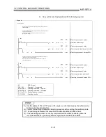
Page 746: ...Specifications subject to change without notice When exported from Japan this manual does not require application to the Ministry of Economy Trade and Industry for service transaction permission HEAD...

Reviews: