7 - 13
MELSEC-A
7 MEMORY CONFIGURATION AND DATA PROCESS
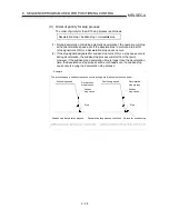
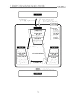
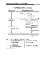
*: About start of communication with the servo amplifier
Communication with the servo amplifier starts when the following two conditions hold.
(Conditions)
•
The AD75 and servo amplifier has been powered on and started.
•
The servo basic parameter "motor capacity" in the AD75 OS memory is other than "0".
(Communication is continued if the servo basic parameter "motor capacity" of the OS memory is set to "0"
after establishment of communication.)
At power-on or PLC CPU reset, the data stored (backed up) in the flash ROM are transferred to the OS
memory. (Refer to section 7.2 (1).)
Therefore, when the servo basic parameter "motor capacity" stored in the flash ROM is not "0" and the servo
amplifier has started earlier than the AD75, communication with the servo amplifier starts before the PLC
CPU starts RUN, so the servo parameters transferred to the servo amplifier are the data stored in the flash
ROM.
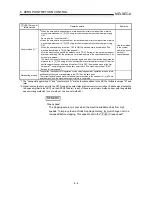
[How to transfer the servo parameters, which were set from the sequence program, to the
servo amplifier]
(Method 1)
Set the value of the servo basic parameter "motor capacity" stored in the flash ROM to "0". (The factory
setting is 0.)
This turns the servo basic parameter "motor capacity" in the flash ROM to "0" at power-on or PLC CPU
reset, disabling communication from starting since the communication starting condition does not hold.
When the servo parameters ("motor capacity" is not "0") are set from the sequence program and the PLC
READY signal [Y1D] is turned from OFF to ON, the servo parameters in the buffer memory are transferred to
the OS memory, and communication starts since the communication start conditions have held.
Therefore, the servo parameters transferred to the servo amplifier are the values set from the sequence
program.
(Method 2)
Turn the PLC READY signal [Y1D] from OFF to ON using the sequence program. When the AD75 READY
signal [X0] then turns from ON to OFF, power on the servo amplifier.
When the AD75 READY signal [X0] turns OFF, the servo parameters set from the sequence program are
reflected on the OS memory.
Therefore, the servo parameters transferred to the servo amplifier are the values set from the sequence
program.
[How to transfer the servo parameters, which were written to the flash ROM, to the servo
amplifier]
Set the servo parameters to the buffer memory and write them to the flash ROM. After that, switch power on
again or reset the PLC CPU.
After the servo parameters to be transferred to the servo amplifier have been written to the flash ROM, the
setting of the servo parameters from the sequence program is not necessary.
Summary of Contents for A1SD75M1
Page 2: ......
Page 20: ...A 18 MEMO...
Page 22: ...MEMO...
Page 27: ...1 5 MELSEC A 1 PRODUCT OUTLINE MEMO...
Page 42: ...1 20 MELSEC A 1 PRODUCT OUTLINE MEMO...
Page 52: ...2 10 MELSEC A 2 SYSTEM CONFIGURATION MEMO...
Page 111: ...5 21 MELSEC A 5 DATA USED FOR POSITIONING CONTROL MEMO...
Page 115: ...5 25 MELSEC A 5 DATA USED FOR POSITIONING CONTROL MEMO...
Page 123: ...5 33 MELSEC A 5 DATA USED FOR POSITIONING CONTROL MEMO...
Page 127: ...5 37 MELSEC A 5 DATA USED FOR POSITIONING CONTROL MEMO...
Page 167: ...5 77 MELSEC A 5 DATA USED FOR POSITIONING CONTROL MEMO...
Page 193: ...5 103 MELSEC A 5 DATA USED FOR POSITIONING CONTROL MEMO...
Page 276: ...5 186 MELSEC A 5 DATA USED FOR POSITIONING CONTROL MEMO...
Page 332: ...7 18 MELSEC A 7 MEMORY CONFIGURATION AND DATA PROCESS MEMO...
Page 334: ...MEMO...
Page 422: ...9 64 MELSEC A 9 MAIN POSITIONING CONTROL MEMO...
Page 446: ...10 24 MELSEC A 10 ADVANCED POSITIONING CONTROL MEMO...
Page 472: ...11 26 MELSEC A 11 MANUAL CONTROL MEMO...
Page 576: ...12 104 MELSEC A 12 CONTROL AUXILIARY FUNCTIONS MEMO...
Page 745: ......

