3 - 3
MELSEC-A
3 SPECIFICATIONS AND FUNCTIONS
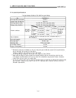
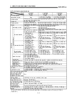
3.2 Performance specifications
Model
Item
A1SD75M1
AD75M1
A1SD75M2
AD75M2
A1SD75M3
AD75M3
No. of control axes
1 axis
2 axes
3 axes
Interpolation function
None
2-axis linear interpolation
2-axis circular interpolation
2-axis linear interpolation
2-axis circular interpolation
Control method
PTP (Point To Point) control, path control (both linear and arc can be set), speed control,
speed/position changeover control
Control unit
mm, inch, degree, pulse
Positioning data
Set with peripheral device
: 600 data (positioning data No. 1 to 600)/axis setting possible
Set with sequence program : 100 data (positioning data No. 1 to 100)/axis setting possible
Backup
Parameters and positioning data can be saved on flash ROM (battery-less).
Positioning method
PTP control
: Incremental method/absolute method
Speed/position changeover : Incremental method
Path control
: Incremental method/absolute method
When system is absolute position detection system (refer to
section 12.6)
When system is not absolute
position detection system
Feedback pulse count = 8192 Feedback pulse count = 16384
Absolute method
•
-214748364.8 to
214748364.7 (
µ
m)
•
-21474.83648 to
21474.83647 (inch)
•
0 to 359.99999 (degree)
•
-2147483648 to
2147483647 (pulse)
•
-26843545.6 to 26843545.5
(
µ
m)
•
-2684.35456 to 2684.35455
(inch)
•
0 to 359.99999 (degree)
•
-268435456 to 268435455
(pulse)
•
-53687091.2 to 53687091.1
(
µ
m)
•
-5368.70912 to 5368.70911
(inch)
•
0 to 359.99999 (degree)
•
-536870912 to 536870911
(pulse)
Incremental method
•
-214748364.8 to
214748364.7 (
µ
m)
•
-21474.83648 to
21474.83647 (inch)
•
-21474.83648 to
21474.83647 (degree)
•
-2147483648 to
2147483647 (pulse)
•
-26843545.6 to 26843545.5
(
µ
m)
•
-2684.35456 to 2684.35455
(inch)
•
0 to 359.99999 (degree)
•
-268435456 to 268435455
(pulse)
•
-53687091.2 to 53687091.1
(
µ
m)
•
-5368.70912 to 5368.70911
(inch)
•
0 to 359.99999 (degree)
•
-536870912 to 536870911
(pulse)
Positioning range
Speed/position
changeover control
•
0 to 214748364.7 (
µ
m)
•
0 to 21474.83647 (inch)
•
0 to 21474.83647 (degree)
•
0 to 2147483647 (pulse)
•
0 to 26843545.5 (
µ
m)
•
0 to 2684.35455 (inch)
•
0 to 359.99999 (degree)
•
0 to 268435455 (pulse)
•
0 to 53687091.1 (
µ
m)
•
0 to 5368.70911 (inch)
•
0 to 359.99999 (degree)
•
0 to 536870911 (pulse)
Speed command
0.01 to 6000000.00 (mm/min)
0.001 to 600000.000 (inch/min)
0.001 to 600000.000 (degree/min)
1 to 1000000 (pulse/s)
Acceleration/
deceleration process
Automatic trapezoidal acceleration/deceleration, S-pattern acceleration/deceleration
Acceleration/
deceleration time
Changeover between 1 to 65535 (ms)/1 to 8388608 (ms) possible
Four patterns can be set each for acceleration time and deceleration time
Positioning
Sudden stop
deceleration time
Changeover between 1 to 65535 (ms)/1 to 8388608 (ms) possible (Same range as
acceleration/deceleration time)
10136-3000VE (soldered type, accessory)
External device connection
connector
10136-6000EL (crimp type, optional)
For 10136-3000VE : AWG#24 to #30 (approx. 0.05 to 0.2 SQ)
Applicable wire size
For 10136-6000EL : AWG#28 (approx. 0.08 SQ)
Max. output command speed 1Mpps
Max. connection distance
between servos (max.
extension distance of
SSCNET connection cable)
30m
Internal current
consumption (5VDC)
A1SD75M : 0.7A or less, AD75M : 0.7A or less
Flash ROM write count
Maximum 100,000 times
E
2
PROM : Maximum 100,000 times
E
2
PROM/FeRAM access
count in absolute position
detection system*
FeRAM : Maximum 9.9999
×
10
9
times
No. of occupied
input/output points
32 points (I/O assignment: special function module 32 points)
Outline dimensions
A1SD75M :130(H)
×
34.5(W)
×
93.6(D)mm , AD75M :250(H)
×
37.5(W)
×
106(D)mm
Weight
A1SD75M : 0.35kg , AD75M : 0.45kg
* Whether E
2
PROM or FeRAM is built in changes depending on the hardware version of the module. (Refer to
Appendix 4.)
Summary of Contents for A1SD75M1
Page 2: ......
Page 20: ...A 18 MEMO...
Page 22: ...MEMO...
Page 27: ...1 5 MELSEC A 1 PRODUCT OUTLINE MEMO...
Page 42: ...1 20 MELSEC A 1 PRODUCT OUTLINE MEMO...
Page 52: ...2 10 MELSEC A 2 SYSTEM CONFIGURATION MEMO...
Page 111: ...5 21 MELSEC A 5 DATA USED FOR POSITIONING CONTROL MEMO...
Page 115: ...5 25 MELSEC A 5 DATA USED FOR POSITIONING CONTROL MEMO...
Page 123: ...5 33 MELSEC A 5 DATA USED FOR POSITIONING CONTROL MEMO...
Page 127: ...5 37 MELSEC A 5 DATA USED FOR POSITIONING CONTROL MEMO...
Page 167: ...5 77 MELSEC A 5 DATA USED FOR POSITIONING CONTROL MEMO...
Page 193: ...5 103 MELSEC A 5 DATA USED FOR POSITIONING CONTROL MEMO...
Page 276: ...5 186 MELSEC A 5 DATA USED FOR POSITIONING CONTROL MEMO...
Page 332: ...7 18 MELSEC A 7 MEMORY CONFIGURATION AND DATA PROCESS MEMO...
Page 334: ...MEMO...
Page 422: ...9 64 MELSEC A 9 MAIN POSITIONING CONTROL MEMO...
Page 446: ...10 24 MELSEC A 10 ADVANCED POSITIONING CONTROL MEMO...
Page 472: ...11 26 MELSEC A 11 MANUAL CONTROL MEMO...
Page 576: ...12 104 MELSEC A 12 CONTROL AUXILIARY FUNCTIONS MEMO...
Page 745: ......


