11 - 17
MELSEC-A
11 MANUAL CONTROL
11.3 Manual pulse generator operation
11.3.1 Outline of manual pulse generator operation
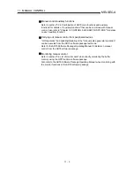
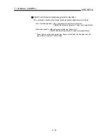
Important
Create the sequence program so that " Cd.22 Manual pulse generator enable flag"
is always set to "0" (disabled) when a manual pulse generator operation is not
carried out.
* Mistakenly touching the manual pulse generator when the manual pulse
generator enable flag is set to "1" (enable) can cause accidents or incorrect
positioning.
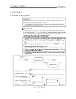
Manual pulse generator operation
In manual pulse generator operation, pulses are input to the AD75 from the
manual pulse generator to output the position/speed command from the AD75 to
the servo amplifier by the number of input pulses, moving the work piece in the
designated direction.
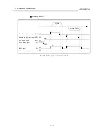
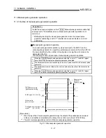
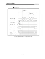
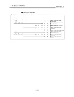
The following shows and example of manual pulse generator operation.
1)
When the " Cd.22 Manual pulse generator enable flag" is set to "1", the BUSY signal
turns ON and the manual pulse generator operation is enabled.
2)
The workpiece is moved corresponding to the No. of pulses input from the manual pulse
generator.
3)
The workpiece movement stops when no more pulses are input from the manual pulse
generator.
4)
When the " Cd.22 Manual pulse generator enable flag" is set to "0", the BUSY signal
turns OFF and the manual pulse generator operation is disabled.
Manual pulse
generator
operation stops
t
BUSY signal [X4, X5, Y6]
Manual pulse
generator input
Positioning start complete
signal [X1, X2, X3]
Manual pulse generator operation enabled
0
OFF
ON
OFF
1) 2)
3)
4)
1
0
Cd 22 Manual pulse
generator enable flag
*
1
*
2
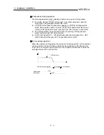
[Precautions]
*
1
When the input from the manual pulse generator stops, the output of the position/speed command
to the servo amplifier is completed with a delay of one control cycle time (120 to 180ms).
*
2
The start complete signal does not turn ON in manual pulse generator operation.
Fig. 11.11 Manual pulse generator operation
Summary of Contents for A1SD75M1
Page 2: ......
Page 20: ...A 18 MEMO...
Page 22: ...MEMO...
Page 27: ...1 5 MELSEC A 1 PRODUCT OUTLINE MEMO...
Page 42: ...1 20 MELSEC A 1 PRODUCT OUTLINE MEMO...
Page 52: ...2 10 MELSEC A 2 SYSTEM CONFIGURATION MEMO...
Page 111: ...5 21 MELSEC A 5 DATA USED FOR POSITIONING CONTROL MEMO...
Page 115: ...5 25 MELSEC A 5 DATA USED FOR POSITIONING CONTROL MEMO...
Page 123: ...5 33 MELSEC A 5 DATA USED FOR POSITIONING CONTROL MEMO...
Page 127: ...5 37 MELSEC A 5 DATA USED FOR POSITIONING CONTROL MEMO...
Page 167: ...5 77 MELSEC A 5 DATA USED FOR POSITIONING CONTROL MEMO...
Page 193: ...5 103 MELSEC A 5 DATA USED FOR POSITIONING CONTROL MEMO...
Page 276: ...5 186 MELSEC A 5 DATA USED FOR POSITIONING CONTROL MEMO...
Page 332: ...7 18 MELSEC A 7 MEMORY CONFIGURATION AND DATA PROCESS MEMO...
Page 334: ...MEMO...
Page 422: ...9 64 MELSEC A 9 MAIN POSITIONING CONTROL MEMO...
Page 446: ...10 24 MELSEC A 10 ADVANCED POSITIONING CONTROL MEMO...
Page 472: ...11 26 MELSEC A 11 MANUAL CONTROL MEMO...
Page 576: ...12 104 MELSEC A 12 CONTROL AUXILIARY FUNCTIONS MEMO...
Page 745: ......

