Appendix - 51
MELSEC-A
APPENDICES
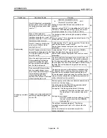
Trouble type
Questions/Trouble
Remedy
No.
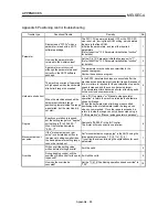
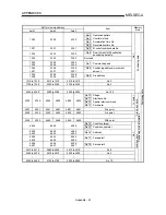
The positioning start signal [Y10] is
kept ON until the BUSY signal is
OFF, but is there any problem with
turning it OFF before the BUSY
signal turns OFF?
After the BUSY signal turns ON, there is no problem with
turning [Y10] OFF before the BUSY signal turns OFF.
(The AD75 detects the rising edge (OFF
ON) of the
positioning start signal [Y10].)
26
Start
The operation will not start even
when the start signal is turned ON.
Check the "
Md.35 axis operation status" and " Md.33
axis error No".
Review the sequence program and normalize the start
timing.
27
How many ms should the axis stop
signal [Y13] be turned ON for?
The signal should be turned ON at 4ms or more.
(If possible, set the signal so it does not turn ON only
momentarily, but instead stays ON until the BUSY signal
turns OFF. This will keep the stop signal from skipping.)
28
How can a sudden stop be
selected?
Set "1: Sudden stop" in the parameter from
Pr.38 to
Pr.40 corresponding to the stop group, and reduce the
setting value of "
Pr.37 Sudden stop deceleration time".
29
Stop
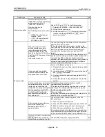
"Normal deceleration stop" was
selected in "
Pr.40 Stop group 3
sudden stop selection", and Y stop
was turned ON. If the
Pr.40
setting is changed to "sudden
stop" during a deceleration stop,
and the Y stop signal turns from
OFF to ON, will the operation
change to a sudden stop from that
point?
The operation will not change.
Even if the same stop factor is input again during the
deceleration stop, it will be ignored. The same
deceleration stop process used when the stop signal was
first input will be continued.
(This also applies for
Pr.38 and Pr.39 .)
30
Circular interpolation
ABS type circular interpolation
operates normally, but a vertically
oblong circle results when INC
type circular interpolation is carried
out.
The address designation may be incorrect. When carrying
out INC type circular interpolation, designate the relative
addresses from the starting point of both the center point
and end point.
31
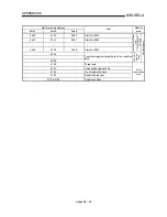
Speed/position
changeover control
Can the speed be changed during
speed control and position control
by speed/position changeover
control?
The speed during speed control and position control
cannot be set separately, but a speed change is possible
if executed after the speed/position changeover signal
turns ON.
32
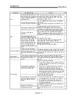
Even if the JOG start signal is
turned ON, the response until it
turns ON is sometimes slow.
Either of the following is possible.
1) The sequence program may be incorrect. Check by
creating a test program in which the JOG start signal
is turned ON only.
2) If the machine is hitting something when the torque
setting is low, it may be trying to move by JOG
operation in the opposite direction. In this case, the
machine will start moving only after the internal droop
pulses have been reached 0 in the counter, even if the
JOG start signal has been turned ON. This makes it
seem that the response is slow.
33
The operation is not carried out at
the set JOG speed, although the
speed limit value has not been
reached.
Either of the following is possible.
1) The JOG start signal may be chattering. Monitor the
JOG start signal to confirm whether it is chattering.
2) The
"
Pr.32 JOG speed limit value" may not be
appropriate. Review the setting value and carry out
the JOG operation again.
34
JOG operation
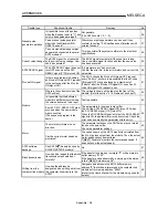
When a JOG operation is
attempted, an error results and the
machine does not move.
The "
Pr.32 JOG speed limit value" may be larger than
the "
Pr.7 Speed limit value".
Review the parameters and carry out the JOG operation
again.
35
Summary of Contents for A1SD75M1
Page 2: ......
Page 20: ...A 18 MEMO...
Page 22: ...MEMO...
Page 27: ...1 5 MELSEC A 1 PRODUCT OUTLINE MEMO...
Page 42: ...1 20 MELSEC A 1 PRODUCT OUTLINE MEMO...
Page 52: ...2 10 MELSEC A 2 SYSTEM CONFIGURATION MEMO...
Page 111: ...5 21 MELSEC A 5 DATA USED FOR POSITIONING CONTROL MEMO...
Page 115: ...5 25 MELSEC A 5 DATA USED FOR POSITIONING CONTROL MEMO...
Page 123: ...5 33 MELSEC A 5 DATA USED FOR POSITIONING CONTROL MEMO...
Page 127: ...5 37 MELSEC A 5 DATA USED FOR POSITIONING CONTROL MEMO...
Page 167: ...5 77 MELSEC A 5 DATA USED FOR POSITIONING CONTROL MEMO...
Page 193: ...5 103 MELSEC A 5 DATA USED FOR POSITIONING CONTROL MEMO...
Page 276: ...5 186 MELSEC A 5 DATA USED FOR POSITIONING CONTROL MEMO...
Page 332: ...7 18 MELSEC A 7 MEMORY CONFIGURATION AND DATA PROCESS MEMO...
Page 334: ...MEMO...
Page 422: ...9 64 MELSEC A 9 MAIN POSITIONING CONTROL MEMO...
Page 446: ...10 24 MELSEC A 10 ADVANCED POSITIONING CONTROL MEMO...
Page 472: ...11 26 MELSEC A 11 MANUAL CONTROL MEMO...
Page 576: ...12 104 MELSEC A 12 CONTROL AUXILIARY FUNCTIONS MEMO...
Page 745: ......


