12 - 45
MELSEC-A
12 CONTROL AUXILIARY FUNCTIONS
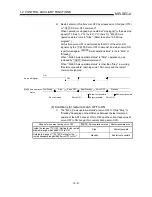
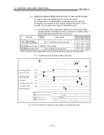
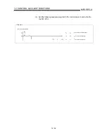
(c) When the speed is changed by setting " Cd.16 New speed value" to "0", the
operation is carried out as follows.
•
A deceleration stop is carried out, and the speed change 0 flag ( Md.40
Status: b10) turns ON.
(During interpolation control, the speed change 0 flag on the reference axis
side turns ON.)
•
The axis stops, but " Md.35 Axis operation status" does not change, and
the BUSY signal remains ON. (If a stop signal is input, the BUSY signal
will turn OFF, and " Md.35 Axis operation status" will change to
"stopped".)
* In this case, setting the " Cd.16 New speed value" to a value besides "0"
will turn OFF the speed change 0 flag ( Md.40 Status: b10), and enable
continued operation.
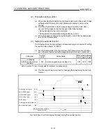
Md. 40 status: b10
Positioning start signal
BUSY signal
Cd. 16 New speed value
Cd. 17 Speed change request
Positioning operation
1000
0
ON
OFF
ON
OFF
ON
OFF
ON
OFF
Speed change 0 flag
[Y10, Y11, Y12]
[X4,X5,X6]
Fig. 12.24 Speed change at new speed value "0"
(d) A warning "deceleration and stop speed change" (warning code: 500)
occurs and the speed cannot be changed in the following cases.
•
During deceleration by a stop command
•
During automatic deceleration during positioning control
(e) A warning "speed limit value over" (warning code: 501) occurs and the
speed is controlled at the " Pr.7 Speed limit value" when the value set in
" Cd.16 New speed value" is equal to or larger than the " Pr.7 Speed limit
value".
(f) When the speed is changed during interpolation control, the required speed
is set in the reference axis.
(g) When carrying out consecutive speed changes, be sure there is an interval
between the speed changes of 100ms or more.
(If the interval between speed changes is short, the AD75 will not be able to
track, and it may become impossible to carry out commands correctly.)
Summary of Contents for A1SD75M1
Page 2: ......
Page 20: ...A 18 MEMO...
Page 22: ...MEMO...
Page 27: ...1 5 MELSEC A 1 PRODUCT OUTLINE MEMO...
Page 42: ...1 20 MELSEC A 1 PRODUCT OUTLINE MEMO...
Page 52: ...2 10 MELSEC A 2 SYSTEM CONFIGURATION MEMO...
Page 111: ...5 21 MELSEC A 5 DATA USED FOR POSITIONING CONTROL MEMO...
Page 115: ...5 25 MELSEC A 5 DATA USED FOR POSITIONING CONTROL MEMO...
Page 123: ...5 33 MELSEC A 5 DATA USED FOR POSITIONING CONTROL MEMO...
Page 127: ...5 37 MELSEC A 5 DATA USED FOR POSITIONING CONTROL MEMO...
Page 167: ...5 77 MELSEC A 5 DATA USED FOR POSITIONING CONTROL MEMO...
Page 193: ...5 103 MELSEC A 5 DATA USED FOR POSITIONING CONTROL MEMO...
Page 276: ...5 186 MELSEC A 5 DATA USED FOR POSITIONING CONTROL MEMO...
Page 332: ...7 18 MELSEC A 7 MEMORY CONFIGURATION AND DATA PROCESS MEMO...
Page 334: ...MEMO...
Page 422: ...9 64 MELSEC A 9 MAIN POSITIONING CONTROL MEMO...
Page 446: ...10 24 MELSEC A 10 ADVANCED POSITIONING CONTROL MEMO...
Page 472: ...11 26 MELSEC A 11 MANUAL CONTROL MEMO...
Page 576: ...12 104 MELSEC A 12 CONTROL AUXILIARY FUNCTIONS MEMO...
Page 745: ......


