Appendix - 39
MELSEC-A
APPENDICES
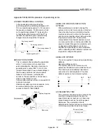
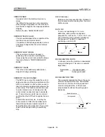
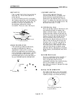
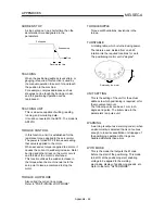
INCREMENTAL ENCODER
A device that simply outputs ON/OFF pulses
by the rotation of the axis. 1-phase types
output only A pulses, and do not indicate the
axis rotation direction. 2-phase types output
both A and B pulse trains, and can judge the
rotation direction. The direction is judged to be
forward if the B pulse train turns ON when A is
ON, and judged to be reverse if A turns ON
when B is ON. There is also another type of
incremental encoder with a zero point signal.
The most commonly used incremental
encoders output between 100 and 10,000
pulses per axis rotation. Refer to "ENCODER".
A
B
A
Z
B
1
4
A signal slit
B signal slit
Slit disk
Light-emitting diode
Phototransistor
Zero signal slit
Rotating axis
1 pitch
pitch
Zero point signal
1 pulse per axis rotation
Output waveform 2-phase + zero point output
INERTIA
The property of an object, when not being
affected by external forces, where it tries to
maintain its current condition. The inertia
moment.
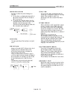
INPUT TERMINAL
This is a pin connector wired by the user for
inputting data to the AD75 from an external
source. It is connected to the machine side.
This terminal is used to output the following.
•
Near-point dog signal
•
Stop signal
•
Upper limit signal
•
Lower limit signal
•
External start signal
•
Speed/position changeover signal
•
Manual pulse generator
The input No. Xn is not directly related to the
program, so it is not used.
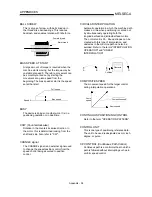
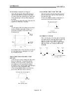
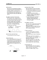
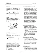
INTERLOCK
In this condition, the machine is blocked from
moving to the next operation until the
operation in progress is complete. This
function is used to prevent damage to devices
and malfunctioning.
Y1
Y0
Y0
Y1
Forward run
Reverse run
INTERPOLATION OPERATION
The operation of two motors simultaneously to
carry out a composite operation. The
positioning distance, acceleration/deceleration
time, speed, etc., for the two motors can be
freely set, but they will be combined to move
the machine in a straight line, circle, etc.
Interpolation operations consist of linear
interpolation and circular interpolation.
INVERTER
This refers to a device to change a direct
current (DC) to an alternating current (AC).
The device actually changes the motor speed
by changing 50Hz or 60Hz of commercial
frequency to direct current once, then
changing it again to a 5 to 120Hz alternating
current and controlling the motor speed.
JOG
This refers to moving the tool in small steps at
a time. Inching.
Parameter setting is required when carrying
out JOG operation.
kPPS
This is the abbreviation for "kilopulses per
second". 80kPPS equals 80,000 pulses per
second.
Summary of Contents for A1SD75M1
Page 2: ......
Page 20: ...A 18 MEMO...
Page 22: ...MEMO...
Page 27: ...1 5 MELSEC A 1 PRODUCT OUTLINE MEMO...
Page 42: ...1 20 MELSEC A 1 PRODUCT OUTLINE MEMO...
Page 52: ...2 10 MELSEC A 2 SYSTEM CONFIGURATION MEMO...
Page 111: ...5 21 MELSEC A 5 DATA USED FOR POSITIONING CONTROL MEMO...
Page 115: ...5 25 MELSEC A 5 DATA USED FOR POSITIONING CONTROL MEMO...
Page 123: ...5 33 MELSEC A 5 DATA USED FOR POSITIONING CONTROL MEMO...
Page 127: ...5 37 MELSEC A 5 DATA USED FOR POSITIONING CONTROL MEMO...
Page 167: ...5 77 MELSEC A 5 DATA USED FOR POSITIONING CONTROL MEMO...
Page 193: ...5 103 MELSEC A 5 DATA USED FOR POSITIONING CONTROL MEMO...
Page 276: ...5 186 MELSEC A 5 DATA USED FOR POSITIONING CONTROL MEMO...
Page 332: ...7 18 MELSEC A 7 MEMORY CONFIGURATION AND DATA PROCESS MEMO...
Page 334: ...MEMO...
Page 422: ...9 64 MELSEC A 9 MAIN POSITIONING CONTROL MEMO...
Page 446: ...10 24 MELSEC A 10 ADVANCED POSITIONING CONTROL MEMO...
Page 472: ...11 26 MELSEC A 11 MANUAL CONTROL MEMO...
Page 576: ...12 104 MELSEC A 12 CONTROL AUXILIARY FUNCTIONS MEMO...
Page 745: ......


