


18-456
18-456
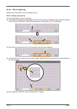
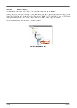
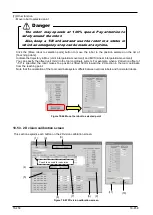
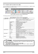
separately are recommended.
Figure 18-63 Example of 9 markers in camera vision (Image)
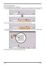
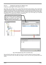
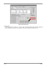
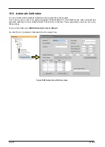
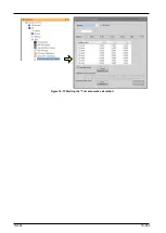
(4) Calculate vision calibration data
When 4 or more data on the list of [Teaching points] are enabled, the [Calculate after selecting 4 points or
more] button becomes enabled. Click the button to calculate the vision calibration data and display the data in
the [Result homography matrix].
Figure 18-64 Calculating vision calibration data
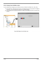
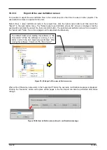
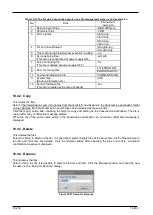
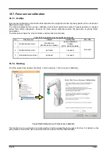
(5) Write to robot
Click the [write to robot] button to write the calculated vision sensor calibration data [VSCALBn] (“n” is the
calibration number) to the robot controller.
As shown in the figure below, the values of the calibration calculation results are displayed at the top, and the
values currently set in the controller are displayed at the bottom for confirmation.
Summary of Contents for 3F-14C-WINE
Page 84: ...8 84 8 84 Figure 8 21 Parameter transfer procedure 1 2 2 ...
Page 393: ...18 393 18 393 Figure 18 1 Starting the Oscillograph ...
Page 413: ...18 413 18 413 Figure 18 24 Output to Robot program Selection ...
Page 464: ...18 464 18 464 Figure 18 72 Starting the Tool automatic calculation ...
Page 545: ...21 545 21 545 Figure 21 55 Hide display of user mechanism ...
Page 624: ...24 624 24 624 Figure 24 4 Document output example ...


