21-554
21-554
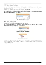
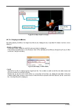
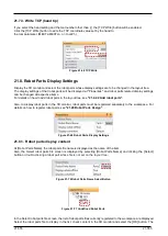
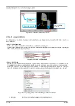
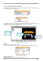
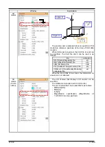
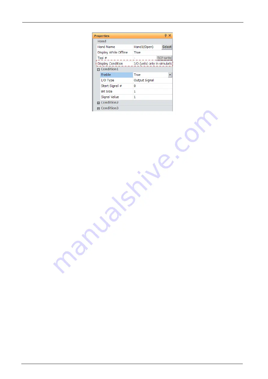
Figure 21-67 Specifying I/O Conditions for Display of Hand Files
- Display conditions
Specify the I/O conditions for displaying the target hand file. This condition is valid only in the simulation mode.
To disable I/O conditions, select [Default], and to enable I/O conditions, select [I/O (valid only in simulation)].
When [I/O (valid only in simulation)] is selected, items [Condition1] to [Condition3] are displayed, and up to
three I/O conditions can be specified. The hand file is displayed when all respective conditions are satisfied.
(1) Enable:
Set [True] for only the number of I/O conditions to set.
When [True] is set, the following items are displayed.
(2) I/O type:
Specify the I/O type.
You can select from [input signal], [output signal], [Register (CC-Link) input] and
[Register (CC-Link) output].
(3) Start signal #:
Specify the I/O start No.
No. 0 onwards can be specified for I/O signals.
No. 6000 onwards can be specified for register (CC-Link) I/O signals.
(4) Bit size:
Specify the number of bits (or number of registers) from the I/O start No.
1 to 32 can be specified for I/O signals. 1 and 2 can be specified for register
(CC-Link) I/O.
(5) Signal value:
Specify the numerical value for comparing with the I/O state.
For I/O signals, specify a value expressed in binary for the bit size using an
unsigned decimal.
For register (CC-Link) I/O, specify a value expressed in binary for one I/O (16-bit
width) or 2 I/O (32-bit width) using a signed decimal.
Summary of Contents for 3F-14C-WINE
Page 84: ...8 84 8 84 Figure 8 21 Parameter transfer procedure 1 2 2 ...
Page 393: ...18 393 18 393 Figure 18 1 Starting the Oscillograph ...
Page 413: ...18 413 18 413 Figure 18 24 Output to Robot program Selection ...
Page 464: ...18 464 18 464 Figure 18 72 Starting the Tool automatic calculation ...
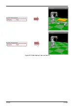
Page 545: ...21 545 21 545 Figure 21 55 Hide display of user mechanism ...
Page 624: ...24 624 24 624 Figure 24 4 Document output example ...

