


21-542
21-542
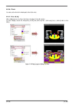
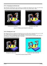
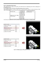
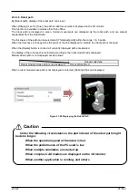
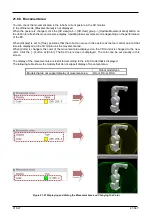
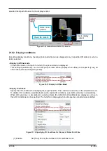
21.6.3.8. Robot path
By [Robot path], display of the robot path can be set.
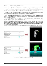
When [Display] is set to [True], the path of robot movement is displayed on the 3D monitor.
This function is available in modes other than offline.
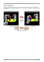
The robot path is displayed in green. Certain movements are displayed as the robot path, and are erased
sequentially from the oldest data.
The thickness of the path can be selected at [Thickness[point]] within the range 1 to 5 points.
When the thickness is changed, the thickness of the line displayed to indicate the robot path is changed.
When the [Delete] button is clicked, all currently displayed paths are deleted.
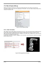
The display of the robot path is restricted according to the robot model that is displayed.
Models whose path is not displayed are as follows.
Robot model type
Robot models whose path is not displayed
RH-G, RC-G, RH-U
When a robot model whose path is not displayed is selected, [Robot path] is not displayed.
Figure 21-52 Displaying the Robot Path
Under the following circumstances, the plot interval of the robot path might
become longer.
When the operation speed of the robot is fast
When the performance of the PC used is low
When multiple simulators are started up
When complex CAD models are displayed on the 3D monitor
When another application is running, and others
Caution
Summary of Contents for 3F-14C-WINE
Page 84: ...8 84 8 84 Figure 8 21 Parameter transfer procedure 1 2 2 ...
Page 393: ...18 393 18 393 Figure 18 1 Starting the Oscillograph ...
Page 413: ...18 413 18 413 Figure 18 24 Output to Robot program Selection ...
Page 464: ...18 464 18 464 Figure 18 72 Starting the Tool automatic calculation ...
Page 545: ...21 545 21 545 Figure 21 55 Hide display of user mechanism ...
Page 624: ...24 624 24 624 Figure 24 4 Document output example ...