13-235
13-235
13.3.15.
Collision avoidance parameters
You can set collision avoidance parameters in the PC and robot controllers.
For details of these parameters, refer to the robot controller's operations manual, See
"Detailed explanations of
functions and operations"
.
13.3.15.1.
Collision avoidance function parameter
Double-click [Movement parameter] -> [Collision avoidance] -> [Collision avoidance function] under the
[Parameter] item to be edited from the project tree.
You can set information related to the Collision avoidance function.
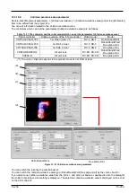
The controllers which can set the parameters [Collision avoidance function] are as follows.
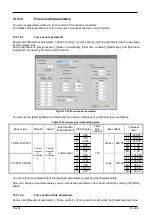
Table 13-12 The controller and the robot model which can set the parameters [Collision avoidance function]
Robot controller
Software version of the robot controller
Robot model
CR800-D(*1)/CR800-R/CR800-Q
All versions
RV-FR, RH-FR
CR750-Q/CRnQ-700
Ver.R3a or later
RV-F, RH-F
CR750-D/CRnD-700(*1)
Ver.S6b or later
RV-F, RH-F
(*1) You can't do the following operations.
・
Click the [Multiple CPU parameter screen] button
・
Set the common coordinates for collision avoidance
・
Click the [Apply from robot arrange of 3D monitor] button
・
Click the [Reflect to robot arrange of 3D monitor] button
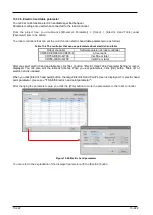
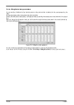
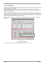
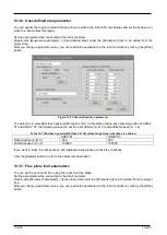
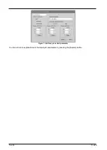
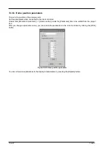
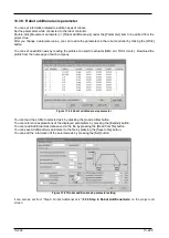
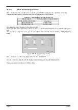
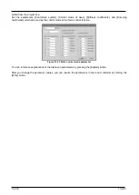
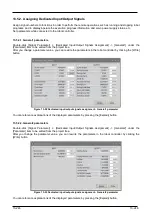
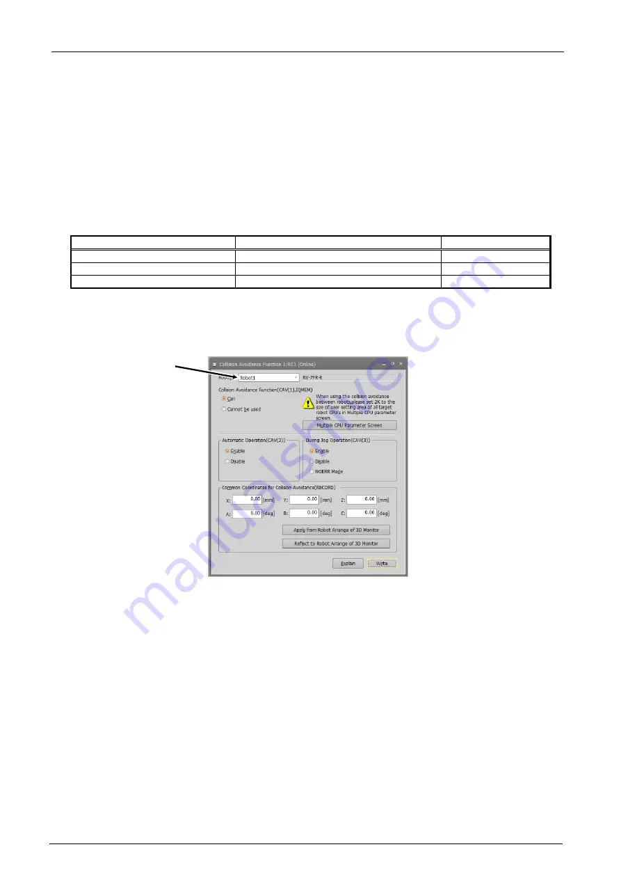
Figure 13-36 Collision avoidance function parameter
You can switch the robot with the combo box<a>.
After you change a parameter values, you can rewrite the parameter in the robot controller by clicking the [Write]
button.
You can show the “Multiple CPU parameter” screen by pressing the [Multiple CPU parameter screen] button.
(You can change the size of user setting area at the “Multiple CPU parameter” screen shown by the operation.)
You can set the coordinates in this screen from the
by pressing the [Apply from robot arrange of
3D monitor] button.
You can update the
from coordinates in this screen by pressing the [Reflect to robot arrange of 3D
monitor] button.
You can reference explanations of the displayed parameters by pressing the [Explain] button.
<a>
Summary of Contents for 3F-14C-WINE
Page 84: ...8 84 8 84 Figure 8 21 Parameter transfer procedure 1 2 2 ...
Page 393: ...18 393 18 393 Figure 18 1 Starting the Oscillograph ...
Page 413: ...18 413 18 413 Figure 18 24 Output to Robot program Selection ...
Page 464: ...18 464 18 464 Figure 18 72 Starting the Tool automatic calculation ...
Page 545: ...21 545 21 545 Figure 21 55 Hide display of user mechanism ...
Page 624: ...24 624 24 624 Figure 24 4 Document output example ...


