20-500
20-500
Cooperative operation simulation setting
When using cooperative action on actual machine, it is necessary to absorb installation error and
manufacturing error. However, there is no error in the virtual space of the simulation, so you can use the following
simple method.
1. Preparation
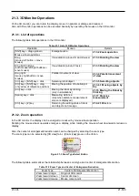
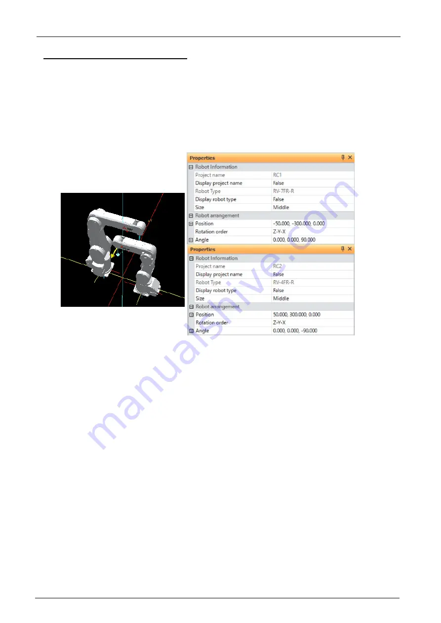
Set up two CR800-R/CR800-Q/CR750-Q/CRnQ-700 Series robots and start the simulation. After that, open the
3D monitor, display the "Robot arrangement list" screen from the "3D View" menu, and place the robot. In this
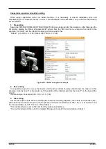
example, the robot 1 and the robot 2 are arranged to face each other.
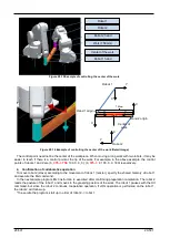
*Robot 1 (-50,-300, 0, 0, 0, 90), Robot 2 (50, 300, 0, 0, 0,-90)
Figure 20-14 Robot arrangement example
2. Base setting
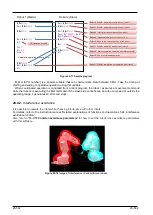
In cooperative operation, one is the master and the other robot is the slave that follows the master. In this
example, since the robot 1 is the master, set "the position of the robot 2 seen from the robot 1" on the base of the
robot 2.
In this example, it becomes (600, -100, 0, 0, 0, 180).
3. Tool setting
Set the tool of two robots. When controlling the center of the work grasped by two robots, set both the robot 1
and robot 2 tools to the work center. In this example, it is the tool coordinates (0, 375, 100, 0, 0, 0) of robot 1 and
the tool coordinates (0, 375, 100, 0, 0, 180) of robot 2.
*The tool Z elements is set to 100 mm from the mechanical interface.
*The tool C elements of the robot 2 is rotated 180 degrees to match the tool direction of robot 1.
Summary of Contents for 3F-14C-WINE
Page 84: ...8 84 8 84 Figure 8 21 Parameter transfer procedure 1 2 2 ...
Page 393: ...18 393 18 393 Figure 18 1 Starting the Oscillograph ...
Page 413: ...18 413 18 413 Figure 18 24 Output to Robot program Selection ...
Page 464: ...18 464 18 464 Figure 18 72 Starting the Tool automatic calculation ...
Page 545: ...21 545 21 545 Figure 21 55 Hide display of user mechanism ...
Page 624: ...24 624 24 624 Figure 24 4 Document output example ...

