3-55
3-55
3.5. Communication Server 2
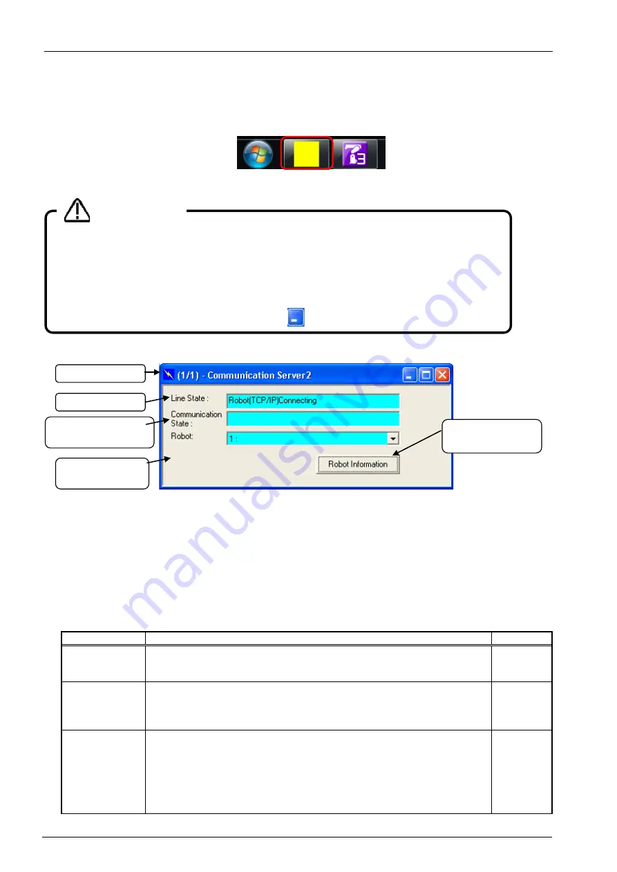
When you start RT ToolBox3, "Communication Server 2" is started up as an icon.
This Communication Server 2 has functions for connecting with a robot controller or, during a simulation, a virtual
controller.
Figure 3-11 Communications Server 2 as Icon
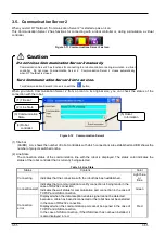
When you return Communication Server 2 from an icon to its original size, you can check the status of the
connection with the robot.
Figure 3-12 Communication Server2
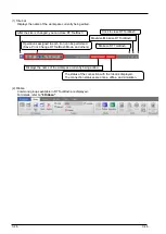
(1) Title bar
(AA/BB) AA: shows the number of robot controllers with which connections are established and BB: shows the
number of projects switched online.
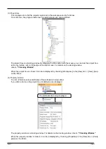
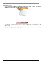
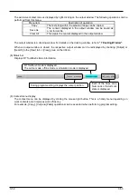
(2) Line State
The connection status of the communication line with the robot is displayed. The status color indicates the
status of the robot controller that is currently being selected.
Table 3-2 Line State
Status
Content
Color
Connecting
Indicates that the connection with the robot has been established.
Light blue
or
Blue
Connection wait
Indicates that a communication to verify connection is being made in the
case of RS-232 connection.
Indicates the wait status for communication port connection in the case of
TCP/IP and USB connection.
Green
Connection
error
Displayed when the data reception enable signal cannot be detected
because a cable has been disconnected or the robot has not been started
in the case of RS-232 connection.
Displayed when the communication port cannot be opened in the case of
TCP/IP and USB connection.
In the case of USB connection, if the USB driver has not been installed, it
is also displayed in red.
Red
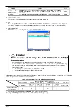
Do not close Communication Server 2 manually.
Communication Server 2 has functions for connecting to a robot controller or during simulation, a virtual
controller. Do not close Communication Server 2. Communication Server 2 closes automatically
when RT ToolBox3 is closed.
Turn Communication Server 2 into an icon.
Turn Communication Server 2 into an icon with the
button.
Caution
(1) Title bar
(2) Line State
(3) Communication
State
(4) Robot
controller
(5) Robot
Information
Summary of Contents for 3F-14C-WINE
Page 84: ...8 84 8 84 Figure 8 21 Parameter transfer procedure 1 2 2 ...
Page 393: ...18 393 18 393 Figure 18 1 Starting the Oscillograph ...
Page 413: ...18 413 18 413 Figure 18 24 Output to Robot program Selection ...
Page 464: ...18 464 18 464 Figure 18 72 Starting the Tool automatic calculation ...
Page 545: ...21 545 21 545 Figure 21 55 Hide display of user mechanism ...
Page 624: ...24 624 24 624 Figure 24 4 Document output example ...

