18-429
18-429
18.3.2.8. Current position data (the joint coordinate system)
The current position data of robot is displayed for each joint coordinate system axis.
To display the current position data (the joint coordinate system) all together, use the "Variable" type and set the
Robot Status Variable "J_CURR". Refer to
for details.
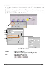
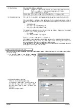
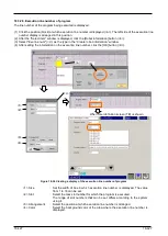
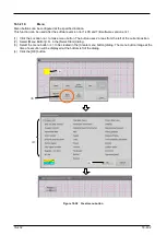
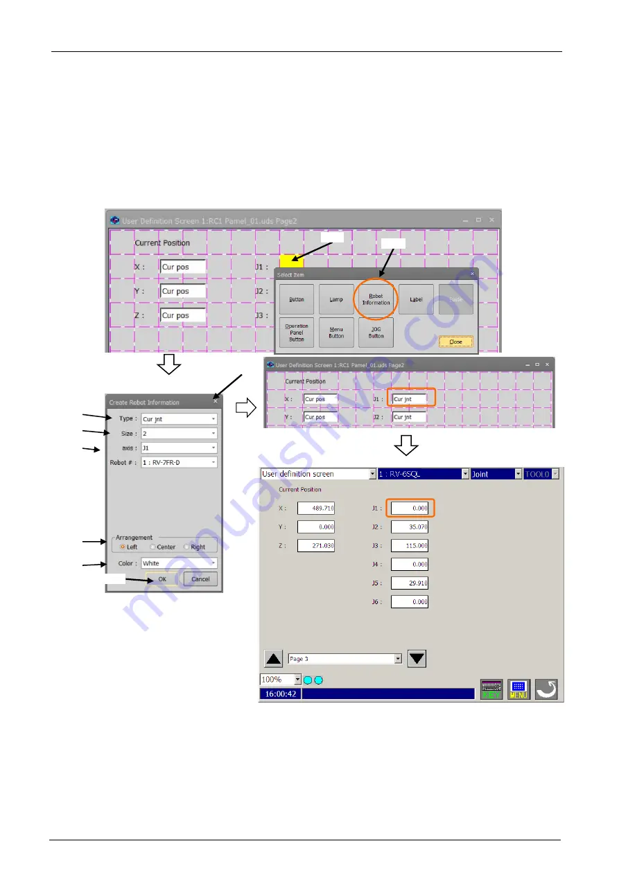
(1) Click the position (block) at which the current position data is displayed (<a>). The left side of the box is
arranged in this position.
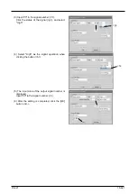
(2) After the "Select item" window is displayed, click the [Robot information] button (<b>).
(3) Select "Cur jnt" (<c>) as the type in the “Create robot information” window.
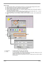
(4) After setting the information on the current position data (the joint coordinate system), click the [OK] button
(<d>).
Figure 18-36 Creating a display of the current position data (the joint coordinate system)
<1> Size
: Set the width of the box in which the current position data (the joint coordinate
system) is displayed. A value from 1 to 16 can be set.
<2> axis
: Select the displayed axis of the current position data (the joint coordinate system).
<3> Robot #
: Select the robot number for which the current position data is displayed.
<4> Arrangement
: Select the position at which the current position data (the joint coordinate system)
is arranged.
<5> Color
: Select the background color of the area where the current position data (the joint
coordinate system) is displayed.
<a>
<c>
<d>
<1>
<2>
<5>
<4>
<3>
When User definition screen (TB) is shown
<b>
Summary of Contents for 3F-14C-WINE
Page 84: ...8 84 8 84 Figure 8 21 Parameter transfer procedure 1 2 2 ...
Page 393: ...18 393 18 393 Figure 18 1 Starting the Oscillograph ...
Page 413: ...18 413 18 413 Figure 18 24 Output to Robot program Selection ...
Page 464: ...18 464 18 464 Figure 18 72 Starting the Tool automatic calculation ...
Page 545: ...21 545 21 545 Figure 21 55 Hide display of user mechanism ...
Page 624: ...24 624 24 624 Figure 24 4 Document output example ...

