9-111
9-111
9.2.6. Travel base setting for display
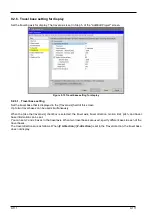
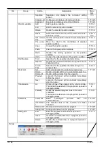
Set the traveling axis for display. The travel axis is set in Step 5. of the "Add/Edit Project" screen.
Figure 9-13 Travel base setting for display
9.2.6.1. Travel base setting
Set the travel base that is displayed in the [Travel axis] field of this screen.
Up to two travel bases can be used simultaneously.
When the [Use the travel axis] checkbox is selected, the travel axis, travel direction, motion limit, pitch, and travel
base information can be set.
You can set J7 and J8 axes to the travel axis. When two travel bases are used, specify different axes to each of the
travel bases.
The travel directions are as follows. When [
Z +direction
]/ [
Z -direction
] is set in the Travel direction, the travel base
does not display.
Summary of Contents for 3F-14C-WINE
Page 84: ...8 84 8 84 Figure 8 21 Parameter transfer procedure 1 2 2 ...
Page 393: ...18 393 18 393 Figure 18 1 Starting the Oscillograph ...
Page 413: ...18 413 18 413 Figure 18 24 Output to Robot program Selection ...
Page 464: ...18 464 18 464 Figure 18 72 Starting the Tool automatic calculation ...
Page 545: ...21 545 21 545 Figure 21 55 Hide display of user mechanism ...
Page 624: ...24 624 24 624 Figure 24 4 Document output example ...


