18-391
18-391
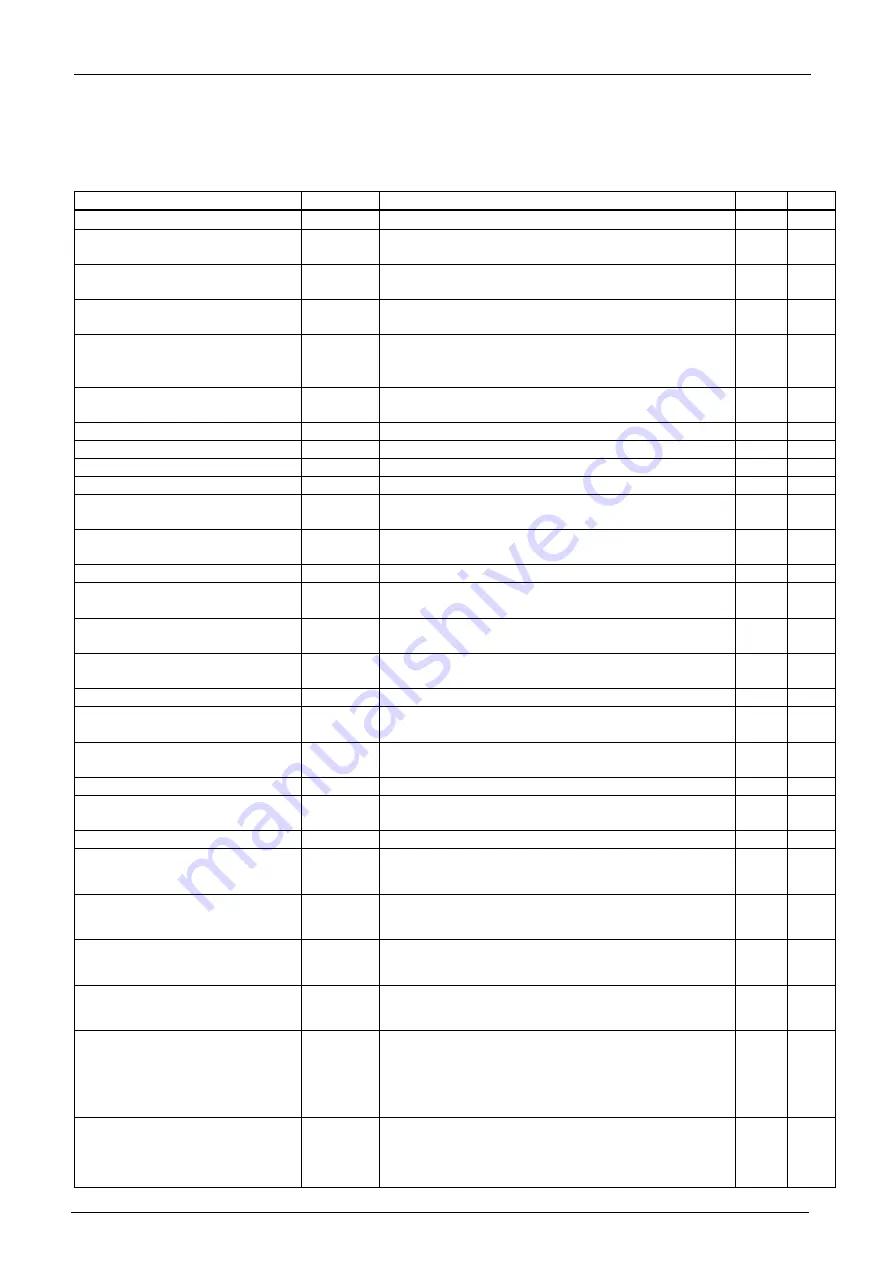
18.1.3. Acquirable data
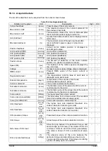
The list of the data that can be acquired from the robot is shown below.
Table 18-3 Oscillograph data list
Notation on the graph
Unit
Explanation
High
Ord
Current feedback
[Arms]
Present value of the motor current.
○
○
Max current cmd2
[Arms]
The maximum value of the current command for
the previous 2 seconds.
-
○
Max current cmd1
[Arms]
The maximum value of the current command after
robot controller power supply is turned on.
-
○
Axis load level
[%]
A preset load ratio of each motor is displayed as an
alarm level.
○
○
Max axis load level
[%]
The maximum value of the axis load level after
robot controller’s power supply is turned on is
displayed.
-
○
Position feedback
[Pulse]
Current motor rotation position is displayed in
encoder pulse value.
○
○
Joint position(CMD)
[mm deg]
Joint position (command)
○
○
XYZ position(CMD)
[mm deg]
XYZ position (command)
○
○
Joint position (FB)
[deg]
Joint position (feedback)
○
-
XYZ position (FB)
[mm deg]
XYZ position (feedback)
○
-
Position droop
[Pulse]
The amount of deflection at the motor rotation
position to a position command is shown.
○
○
Speed (FB)
[rpm]
The feedback of the motor speed is displayed by
the unit of rpm.
○
○
Voltage
[V]
A present power-supply voltage value is displayed.
○
○
RMS current
[Arms]
Present RMS value of the motor current is
displayed.
○
-
Regeneration level
[%]
The regenerative current value of each axis is
displayed as an alarm level.
○
○
Encoder temperature
[deg C]
Temperature of the encoder of each axis
Correspondence since F series.
○
○
Current command
[Arms]
The current command of the motor.
○
○
Tolerable c
[Arms]
The limitation value of the plus side of the current
command set to the motor.
○
○
Tolerable command -
[Arms]
The limitation value of the minus side of the current
command set to the motor is displayed.
○
○
Force sensor
[N Nm]
The input value from a force sensor.
○
-
Force resultants)
[N Nm]
The input value from a force sensor (The resultant
force and resultant moment values exist).
○
-
Force pos CMD(XYZ)
[mm rag]
Force sense position command(XYZ)
○
-
COL thr
[0.1%]
rated
current
The higher rank side detection threshold of a
collision detection function (plus side)
○
-
COL threshold -
[0.1%]
rated
current
The higher rank side detection threshold of a
collision detection function (minus side)
○
-
COL presumed torque
[0.1%]
rated
current
Presumed torque of the collision detection function.
○
-
COL torque
[0.1%]
rated
current
Actual torque of the collision detection function.
○
-
Ref. value of COL level
[%]
Show the gap between the estimated torque and
actual torque by COL level (The values of COLLVL
command, COLLVL and COLLVLJG parameters).
The value is shown if COL is enabled and servo
ON.
○
-
Error of presumed torque
[%
rating]
The absolute value of the error between the
estimated torque and actual torque of each axis.
You can get this value only if the torque monitoring
function of safety option is enabled.
○
-
Summary of Contents for 3F-14C-WINE
Page 84: ...8 84 8 84 Figure 8 21 Parameter transfer procedure 1 2 2 ...
Page 393: ...18 393 18 393 Figure 18 1 Starting the Oscillograph ...
Page 413: ...18 413 18 413 Figure 18 24 Output to Robot program Selection ...
Page 464: ...18 464 18 464 Figure 18 72 Starting the Tool automatic calculation ...
Page 545: ...21 545 21 545 Figure 21 55 Hide display of user mechanism ...
Page 624: ...24 624 24 624 Figure 24 4 Document output example ...

