21-598
21-598
21.20. Robot Parts Design
Robot parts are displayed on each axis of the robot on the 3D monitor
and the robot parts to display can be
switched according to signal state, for example.
Robot parts
that you design are registered to the workspace. For this reason,
robot parts
must be designed
before
robot parts
display settings are made on the layout tree. Create the
robot parts
file to be used and then
make the display settings on the layout tree.
21.20.1.
Robot parts
file manager
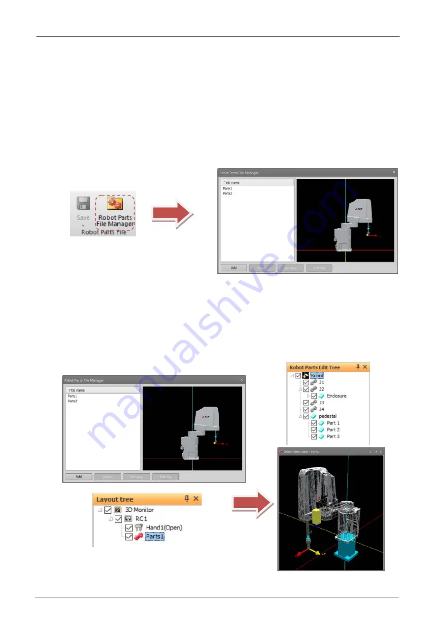
Click the [3D view] tab -> [
Robot Parts
File] group -> [
Robot Parts
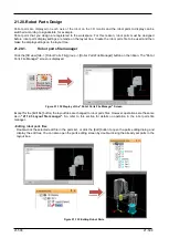
File Manager] button on the ribbon. The "R
obot
Parts
File Manager" screen is displayed.
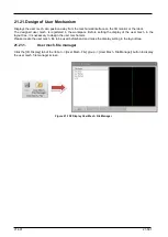
Figure 21-132 Display of the "R
obot Parts
File Manager" Screen
Except for the [Edit file] button, the layout files are changed to
robot parts
files. However, operations are the same
as in
. So, refer to this section for details on operation in the
robot parts
file
manager.
- Editing
robot parts
files
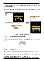
Double-click the selected edit file in the parts list, or click the [Edit] button to open the parts editing dialog and
display the edit tree. You can also open the parts editing screen by double-clicking the already set parts in the
layout tree.
Figure 21-133 Editing Robot Parts
Summary of Contents for 3F-14C-WINE
Page 84: ...8 84 8 84 Figure 8 21 Parameter transfer procedure 1 2 2 ...
Page 393: ...18 393 18 393 Figure 18 1 Starting the Oscillograph ...
Page 413: ...18 413 18 413 Figure 18 24 Output to Robot program Selection ...
Page 464: ...18 464 18 464 Figure 18 72 Starting the Tool automatic calculation ...
Page 545: ...21 545 21 545 Figure 21 55 Hide display of user mechanism ...
Page 624: ...24 624 24 624 Figure 24 4 Document output example ...

