Install Telecommunications Cabling
Cable Installation
412
SI Installation and Upgrades
June 2004
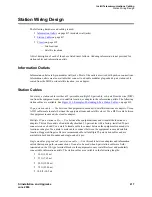
Equipment Room Cabling Labels
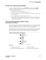
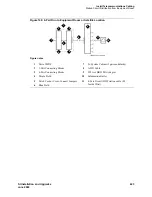
The purple port label shown in
Figure 140, Equipment Room Cabling Labels,
on page 413 is installed on
both ends of the 25-pair cables connecting to the trunk/auxiliary field and/or distribution field.
The top blue/yellow building and floor labels are for cables connecting from the equipment room to a
site/satellite location on another floor or in another building. The yellow label is for auxiliary circuits
connecting to the trunk/auxiliary field. The bottom blue/yellow label is for 25-pair cables connecting to
site/satellite closets.
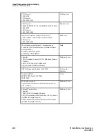
Equipment Room Labels
on page 414 details the label name and range of each label.
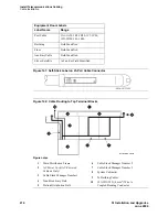
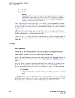
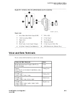
Figure 141, Self-Stick Label on 25-Pair Cable Connector,
on page 414 shows the proper way to install a
label on a 25-pair cable connector. Install the label near the rear of the connector so it is not obscured by
the cabinet connector retainers. It can also be installed on the skin of the cable near the connector.
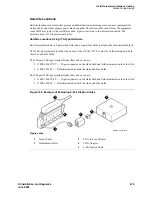
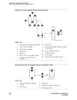
Cable Routing Guidelines
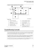
Figure 142, Cable Routing to Top Terminal Blocks,
on page 414 and
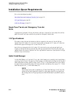
Figure 143, Cable Routing to
Bottom Terminal Blocks,
on page 415 show typical cable routing from the cabinet to the top and bottom
of the MDF, respectively.
Use these guidelines when routing cables from the cabinet to the MDF. Following these guidelines will
maximize use of the cable slack managers and make future cabling additions and changes easier.
•
Connect each port cable at the cabinet, and then route it along the front trough of the cable slack
manager to the connecting/terminal block, where the cable is terminated.
•
Leave enough slack at the cabinet end of the cable to allow for proper dressing of the cables.
•
Route the cable from the cabinet to the wall. Place the cable beside 1 of the rows of columns in the
cable slack manager.
NOTE:
Retainers mounted on the columns keep the cable from protruding above the top of the
base of the cable slack manager.
•
Determine the length of the cable required to reach from the cable slack manager to the assigned
connecting/terminal block.
•
Use D rings on the wall to support the cable. (The cable must be supported.)
•
Coil the cable around the columns in the cable slack manager to store cable slack. The first run
should always go across the full length of the 5 columns in the cable slack manager.
•
Connect the cable to the assigned connecting/terminal block.
•
Avoid placing copper cables where they may bend or strain fiber optic cables.

