Install and Connect Modems
Task List: Install and Connect Modems
706
SI Installation and Upgrades
June 2004
7
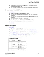
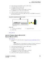
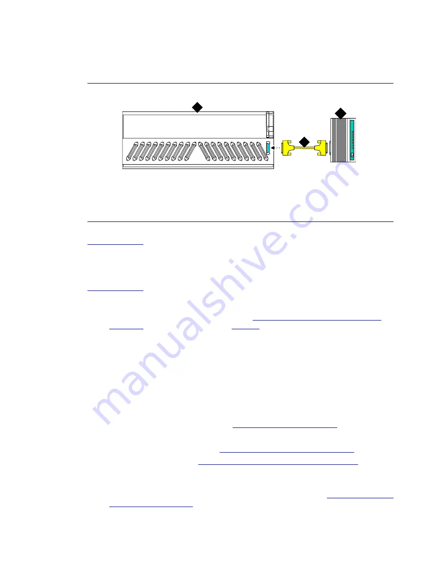
Disconnect the RS-232 cable from the terminal and connect it to the TERMINAL connector on
the rear of the system cabinet.
Figure 286: Connect External Modem to PPN
Return to Task List
Add External Modem to TN1648B
Return to Task List
Use a type-approved external modem.
1
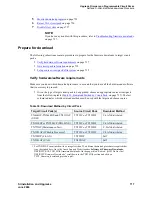
Unpack and inspect the equipment received. See
Figure 287, External Modem Pass-Thru Kit
Equipment,
on page 707 for the parts and
Parts List
on page 708 for a list of parts. Actual
equipment may vary in appearance and may ship in separate packages.
2
Open the front door.
NOTE:
Administration may be required before removing the circuit pack in the following step.
3
Determine which slot will contain the new circuit pack. Remove the circuit pack or the apparatus
blank from this slot.
4
Install the new circuit pack.
5
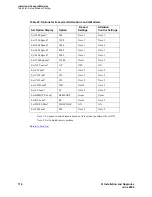
From the front, remove the fan cover. See
Figure 288, Remove the Fan Cover,
on page 708.
6
Open the rear door.
7
Attach the panel adapter bracket. See
Figure 289, Attach the Panel Adapter Bracket,
on page 709.
8
Insert the cable assembly. See
Figure 290, Attach the Cable Assembly to the Bracket,
on page
709.
9
Connect the external modem cable to the cable assembly.
10
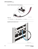
Attach the RJ45 (telephone plug) to the pass-thru tool using a tie wrap. See
Figure 291, Attach the
Cable to the Pass-Thru Tool,
on page 710. If you are using only one RJ45, bundle the other one
and tie wrap it near the body of the cable assembly.
Figure notes
1
U.S. Robotics External Modem
2
RS-232 Cable
3
Processor Port Network
cydfepnm KLC 100397
TERMINAL
1
2
3


