Install and Wire Telephones
Task List: Connect Voice and Data Terminals
SI Installation and Upgrades
503
June 2004
4
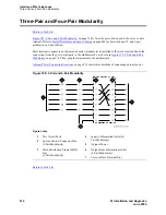
Install cross-connect jumpers to wire the terminal to the port circuit pack. See
Figure 192, 302C1
to 4-wire DCP Wiring,
on page 503. This pinout is for the 4-wire Digital Line circuit pack.
CAUTION:
Do not use the 329A power unit for the attendant console. Use an 1151A1, 1151A2,
1145A, or MSP-1 power unit.
5
For terminals needing adjunct power, wire -48 VDC and ground to appropriate pins on the
terminal. See
Figure 192
.
Figure 192: 302C1 to 4-wire DCP Wiring
Return to Task List
Connect Adjunct Power
Return to Task List
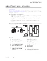
The 400B2 adapter is convenient for connecting local -48 VDC power to a modular plug. See
Figure 193,
400B2 Adapter Connecting to a Modular Plug,
on page 504.
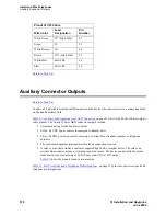
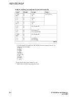
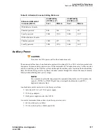
Each port network can provide power for up to three attendant consoles. This source of power is preferred
for the attendant consoles because it has the same battery backup as the system. See
Auxiliary Connector
Outputs
on page 510.
NOTE:
Adjunct power can be provided locally at the telephone or console by either the 1151A1
or 1151A2 power supply. Adjunct power can be provided from the equipment room or
equipment closet with the 1145B power unit. Go to
Install and Wire Telephone Power
Supply
on page 549 for power supply information and installation procedures.
Figure notes
1
302C1 Attendant Console
2
4-wire Digital Line Circuit Pack (Position 1C02)
3
-48 VDC From Adjunct Power
4
Ground From Adjunct Power
302cwire RBP 040596
1
39
14
40
15
2
3
6
7
8
TXT
TXR
PXT
PXR
TXT5
TXR5
PXT5
PXR5

