Add IP Solutions
Task list: Install the TN802B in Media Processor mode
SI Installation and Upgrades
619
June 2004
Connect the Cables for TN802B
Return to Task List
1
Determine into which port slot you are putting the TN802B IP Interface.
NOTE:
Make sure that at least 3 adjoining slots are free.
2
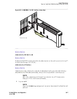
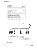
From the rear of the cabinet, connect the amphenol connector on the external cable assembly to
the backplane connector corresponding to that slot (the highest numbered connector of the 3 slots
required).
Connect the Modem
Return to Task List
NOTE:
These instructions are for connecting the U.S. Robotics modem supplied to U.S.
customers only. If using a different modem, follow the manufacturer’s instructions on
connecting the modem.
1
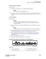
Connect the RS232 port of the modem to the MODEM connector of the TN802B external cable
assembly.
NOTE:
Check the labels near the connectors; the MODEM and COM2 connectors look the same.
2
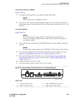
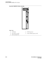
Connect an analog telephone line to the left most analog-line port on the modem as shown in
Figure 241, External Modem Connections for U.S. Robotics Modem,
on page 619.
3
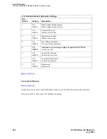
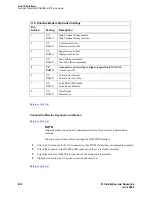
Make sure that the modem’s DIP switches are set as shown in
Figure 241, External Modem
Connections for U.S. Robotics Modem,
on page 619 and
U.S. Robotics Modem Dip Switch
Settings
on page 620.
4
Plug the modem into an AC power outlet.
5
Turn on the modem using the switch on the front of the modem.
Figure 241: External Modem Connections for U.S. Robotics Modem
Figure notes
1
Connect analog line here.
2
DIP switch 5 must be up.
3
Connect MODEM connector here.
4
Connect power connector here.
1 2 3 4 5 6 7 8
modfrobo KLC 030499
2
3
4
1


