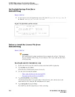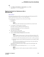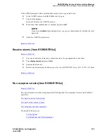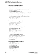
R5/R6/R7/R8si to Avaya Communication Manager
Task List: R5/R6/R7/R8si to Avaya Communication Manager
SI Installation and Upgrades
119
June 2004
1
Remove the following equipment:
— Translation card from the TN777B or TN794
— TN790/B processor circuit pack
— TN778 packet control circuit pack
— TN777B network control or TN794, TN794/TN2400 NetPkt circuit packs
2
Store each component separately in anti-static packing material.
NOTE:
Keep original translation card nearby.
Return to Task List
Remove TN765 circuit pack [from
R5/R6/R7/R8si]
Return to Task List
1
Remove the TN765 processor interface circuit pack if no bx.25 links were administered and the
customer does not plan on using them in the future.
Replace TN772 duplication interfaces with the
TN792 duplication interfaces (R6si or earlier)
[from R5/R6/R7/R8si]
Return to Task List
1
Remove the TN772 Duplication Interface circuit packs and place them in antistatic packing
material.
Leave the existing duplication cables connected to the backplane. The fiber optic cable
connecting the new TN792 Duplication Interface circuit packs does not replace these cables.
2
Insert the TN792 Duplication Interface circuit packs into the slots labeled DUPN INTFC.
3
If the carrier is located in a Multicarrier Cabinet (MCC1), attach the 14-in. fiber optic cable to the
faceplates of the installed TN792 Duplication Interface circuit packs (see
Figure 1, Fiber optic
cable connecting the two TN792 duplication interface circuit packs (multicarrier cabinet only),
on
page 120).
or
If the carrier is in a Single-Carrier Cabinet (SCC1), then attach the 10-ft fiber optic cable to the
faceplates of the installed TN792 Duplication Interface circuit packst.

