G3V4vs/R5vs/R6vs to Avaya Communication Manager
Task List: DEFINITY vs to Avaya Communication Manager
158
SI Installation and Upgrades
June 2004
Move circuit packs from G3V4vs/R5vs/R6vs
Return to Task List
1
Label each port circuit pack in the G3V4vs with its slot number.
2
Remove all circuit packs from the G3V4vs. Store the circuit packs in the static-proof packaging.
3
Remove and keep all circuit pack blanks.
4
Install the power unit and the remaining control circuit packs into the new si cabinet.
5
Install the port circuit packs into their corresponding slots in the control cabinet.
The new control cabinet has more port slots than the G3V4vs cabinet so you should not need to
retranslate these circuit packs.
6
Install blank face plates in any vacant slots.
7
Insert the old translation card into the Net/Pkt interface circuit pack.
Return to Task List
Verify TDM cables and connectors [from
G3V4vs/R5vs/R6vs]
Return to Task List
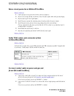
Verify that the system has the correct TDM/LAN cables and TDM terminators installed. Using this table
as a reference, visually inspect the PPN and EPN connections.
Return to Task List
Connect control cabinet power and ground
[from G3V4vs/R5vs/R6vs]
Return to Task List
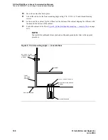
1
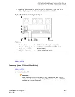
Connect the 6 AWG (#40) (16-mm
2
) wire from the single-point ground block on the control
cabinet to the approved ground (see
Typical AC power and ground layout
).
This wire was previously used on the DEFINITY vs cabinet.
2
Connect the 10 AWG (#25) (6-mm
2
) wire between the cabinet single-point ground block and the
CBC.
This wire was previously used on the DEFINITY vs cabinet.
Cabinet
TDM/LAN cable
TDM Terminator
SCC1
WP-91716 L3
AHF110
MCC1
WP-91716 L6 and L7 (older cables have blue
labels; yellow labels are newer)
ZAHF4


