Install and Connect MCC1 (Multicarrier) Cabinet
Task List: Connect DC Power and Ground
SI Installation and Upgrades
347
June 2004
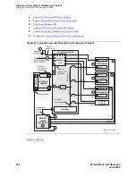
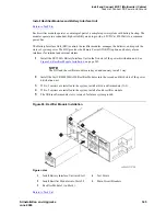
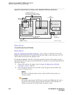
Figure 98: Typical Cabinet Grounding Wiring Diagram
Return to Task List
Install Coupled Bonding Conductor Wires
Return to Task List
This is a conductor that connects to the single-point ground block and run adjacent to pairs in an
associated cable. The mutual coupling between the CBC and the pairs reduces potential differences in
terminating equipment. The conductor consists of a 10 AWG (#25) (6 mm
2
) wire terminated at the CBC
ground terminal bar at the Main Distribution Frame (MDF).
1
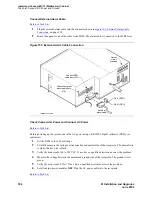
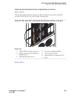
At the DC Power Cabinet, connect a 10 AWG (#25) (6 mm
2
) ground wire to the Ground
Discharge Bar. See
Figure 95, Typical Power and Ground for a DC-Powered Cabinet,
on page
344.
2
Route the 10 AWG (#25) (6 mm
2
) ground wire to the CBC ground terminal bar at the MDF. Be
sure a minimum of 12 in. (30.5 cm) spacing is maintained between the CBC and other power and
ground leads.
Figure notes
1
PPN Cabinet
2
EPN Cabinet (if Installed)
3
6 AWG (#40) (16 mm2)
CABINET GROUND Wire
4
Single-Point Ground Block
5
6 AWG (#40) (16 4 mm2) Ground
Wire to Approved Ground
6
AC Load Center Single-Point Ground
7
Over 50 ft (15.2 m)
8
Cabinet Ground Terminal Block
6
1
2
2
3
3
3
5
widfspgb KLC 100297
7
4
8
8
8


